Day 30. Motherboard Components
CompTIA A+ 220-901 Exam Topics
- Objective 1.2: Explain the importance of motherboard components, their purpose, and properties.
- Objective 1.3: Compare and contrast various RAM types and their features.
Key Topics
In this day, we will explore all the motherboard components. We will discuss the purpose of each component and its properties. We also will discuss the various types of RAM and the features of each.
Motherboards
All the electrical components and devices that comprise a computer connect to a main circuit board called the motherboard. The motherboard provides sockets for plugging in components and electrical pathways between these components, called busses.
Sizes/Form Factors
Motherboards come in many sizes and shapes. The size and shape is known as the form factor of the motherboard. The form factor also dictates the number and layout of the components the motherboard can have. The smaller the board, the less components it can have.
The form factor of the motherboard also can dictate the size and shape of the case in which it is installed. It is important to match the correct power supply with the motherboard. Some connectors might not fit, and the power supply might not fit in the designated case for the motherboard. Table 30-1 summarizes the main form factors for motherboards in use today.
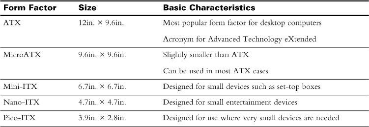
Table 30-1 Motherboard Form Factors
Choosing the Correct Motherboard
The right motherboard is based on the application to which it will be used. Small devices, or those where many expansion slots are not needed, can use smaller motherboards. Other factors such as the components that will be installed will dictate the correct motherboard to use. The following factors determine what motherboard to use:
- CPU socket type—The central processing unit (CPU) socket must support the CPU that is being used, along with the heat sink and fan assembly.
- Chipset and capabilities—Newer chipsets offer newer technology and support of newer and faster CPUs.
- Type and number of RAM slots—Make sure that there are enough slots to accommodate the amount of RAM that will be needed and that the motherboard supports the intended RAM speed.
- Bus—For a 64-bit operating system, or to support more than 4GB RAM, a 64-bit bus is required.
- Type and number of expansion slots—Be sure to accommodate for any necessary features for the computer such as advanced video cards running in tandem.
- Size—The size will dictate the case. It must fit in the current case; otherwise, a new case will need to be used.
Documentation
Most motherboards come with a user manual. The manual is important—especially when sourcing the CPU and RAM, but also during the initial setup and installation of the board. The manual will show you where all the components are, the specifications of these components, and any special instructions for installation.
The manual also will come in handy for troubleshooting the hardware and upgrading components in the future.
Identification of Components
You need to be able to identify all the components of a motherboard. Some items might look similar to others but are not compatible.
Figure 30-1 shows a motherboard with many of the main components labeled.
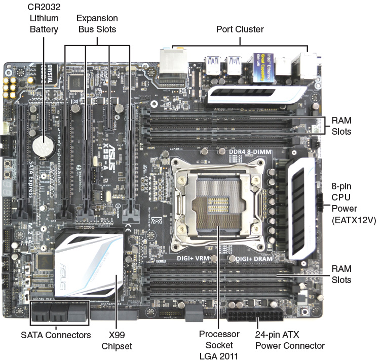
Figure 30-1 Motherboard
 Activity 30-1: Match the Motherboard Components to Their Location
CPU Sockets
The CPU socket is where the CPU is installed on the motherboard. Electrical contacts align with those on the CPU package, and a retaining arm locks the CPU in place. The socket also provides for the attachment of the heat sink and fan assembly on top of the CPU package. This system enables easy replacement and upgrading of the CPU.
Types
There are two main types of CPU sockets in use today: the pin grid array (PGA) and the land grid array (LGA). Both of these sockets are zero insertion force (ZIF) sockets. A ZIF socket enables the installation of the CPU without using any force to install it. The CPU is simply placed in the socket easily and locked into place with a mechanical retaining device.
The PGA socket has pinholes that align to pins on the underside of the CPU package. The LGA socket has very small contact points that are raised slightly. These contact points align with contact points on the underside of the CPU package. The LGA socket has less chance of being damaged during installation or removal.
The most important aspect of the CPU socket is compatibility with the CPU. Both the CPU and the socket must be of the same type. The heat sink fan assembly also must be compatible with the socket and CPU. Table 30-2 shows some of the more popular CPU sockets and the CPUs that can be used with them.
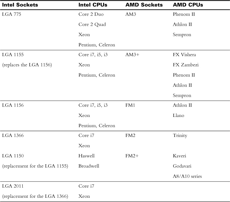
Table 30-2 CPU Socket Details
Chipsets
All the components on the motherboard communicate through integrated circuits called the chipset. The chipset controls how the hardware, CPU, and motherboard interact. It is responsible for the capabilities of these components, such as support for USB types, the type and amount of RAM, and which CPU can be used. The chipset connects all the hardware components together. Figure 30-2 shows how all these components are connected.
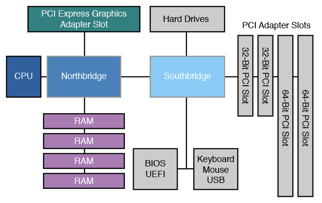
Figure 30-2 Motherboard Component Connections
Types
Historically, chipsets were made up of two different chips, the northbridge and the southbridge. Today, it is common to find a southbridge chip with the functionality of the northbridge chip built in to the processor itself.
The northbridge controls device connections that require high speed and transfer rates. RAM and video cards are the most common type of devices connected to the northbridge. The northbridge also connects the CPU to the southbridge. In some instances, the northbridge is integrated with the processor.
The southbridge controls the connections to all the secondary controllers. These include SATA, USB, audio, and other expansion slots and peripherals.
Clock Rates
Communications within a computer are performed electrically. The speed at which the communication happens is known as a clock rate and is determined by the motherboard. There are two basic clock rates in a computer:
- The bus speed, or base clock
- The CPU speed, or internal clock speed
Bus Speeds
On the motherboard, data travels between components using a bus. The bus is divided into two parts—the data bus and the address bus. The data bus carries data between all the computer components, whereas the address bus carries the memory addresses of the data.
The motherboard has a clock that determines the speed of the bus. Not to be confused with the clock that keeps the date and time, this clock is a quartz crystal that oscillates at a specific speed, in MHz. This speed is the bus speed of the motherboard.
The amount of data that can be transmitted on the bus at one time depends on the bus width. The bus width can be 32-bit or 64-bit.
CPU Speed
The internal clock speed is the speed of the CPU. The bus speed of the motherboard is multiplied to determine CPU speed. A CPU with a speed of 4.0 GHz, such as the Intel Core i7-6700K, installed on a motherboard with a 100 MHz bus speed would have a multiplier of 40.
The term overclocking is used to describe increasing the multiplier or bus speed to increase the CPU speed. Increasing the multiplier will increase the CPU speed, whereas increasing the bus speed will not only increase the speed of the CPU, but also the speed at which the RAM operates. To overclock, voltages are increased, in turn, increasing heat within components. Overclocking can lead to damaged RAM and CPU or a decrease in life expectancy of these components.
RAM Slots
Memory is where the data is stored to and retrieved from. This memory is in the form of circuit boards with memory integrated circuits attached, often called sticks. These RAM sticks are installed in the RAM slots. There are many types of RAM and RAM slots with different characteristics, sizes, and speeds. The memory controller is responsible for data flow between the RAM and CPU.
The most common form of memory stick is dynamic RAM (DRAM). DRAM is volatile memory—the contents of the memory are not retained unless the memory is receiving power. When the computer is turned off, the memory stick is erased.
One of the most common ways to increase the capability of a computer is to increase the amount of RAM. When the CPU has a lot of RAM, it does not need to access slower memory such as a hard drive as often. More programs and more data files can be held in RAM at the same time, making multitasking much faster.
Two main sizes of RAM sticks are in use in computers today: Dual Inline Memory Module (DIMM) and Small Outline DIMM (SODIMM). The DIMM is used in desktop computers, and the smaller SODIMM is used in laptop computers.
Types
The following RAM types are not compatible. Each has a different number of pins, different voltage requirements, and physical differences that prevent them from being interchanged.
DDR
This type of memory is synchronized to the speed of the motherboard or clock, but it transfers data on the rising and falling of the signal. This doubles the amount of data the RAM can transfer per cycle. DDR DIMM memory runs at 2.5 V and has 184 pins.
DDR2
By using a faster signal, this type of RAM provides four transfers per cycle. DDR2 DIMM memory runs at 1.8 V and has 240 pins.
DDR3
This type of RAM has two transfers per cycle, but the clock speed is quadrupled, resulting in a multiplier of 8. DDR3 DIMM memory runs at 1.2–1.5 V and has 240 pins.
Single-Channel RAM
A 64-bit bus resides between the RAM and the memory controller for the transfer of data. This is a single-channel configuration.
Dual-Channel RAM
Data throughput is doubled in this configuration because there are two completely separate channels to make a 128-bit bus. RAM sticks are installed in separate banks; these are color-coded to show which ones are connected to which channel.
Triple-Channel RAM
Three RAM sticks, or a multiple of three, are used to increase the speed of the RAM. When storing data, the CPU alternates between modules, tripling the bandwidth.
RAM Characteristics
Parity versus Non-parity
Parity RAM stores an extra bit for each byte that is used for error detection. When the byte is written, the bits are added. If the number of bits is odd, the parity bit is not turned on. If the number of bits is even, the parity bit is turned on. When the data is read, the parity bit is compared against the byte to determine whether the byte has changed.
ECC versus Non-ECC
Error correction code (ECC) RAM implements an algorithm on 8 bytes of data at a time. The algorithm produces an 8-bit word. When the data is read, the algorithm is performed again. If the data has changed, it can be corrected by using the 8-bit word. Most RAM does not use this algorithm and is considered non-ECC.
Single-sided versus Double-sided
It is a common misconception that double-sided RAM is where the RAM chips are attached to both sides of the stick. Single-sided RAM has a single bank of chips. All the chips in the bank can be accessed by the CPU at the same time. Double-sided RAM has two banks of chips that are accessed individually.
Buffered versus Unbuffered
Buffered RAM uses a storage location, or buffer, between the modules and the memory controller. Buffered RAM increases the stability of a computer that has many memory modules. Most RAM does not have this additional buffer and is considered unbuffered.
Expansion Slots
To add functionality to a computer, expansion cards are added in expansion slots. The two prominent types of expansion slots in use are Peripheral Component Interconnect (PCI) and PCI Express (PCIe). Expansion cards can provide video, audio, network, storage, or additional ports for the computer.
Types and Properties
PCI
The PCI bus connects expansion cards to the southbridge. This limits the communication speed between the CPU and the expansion cards connected to this bus.
PCIe
The PCIe bus can connect to either the southbridge or the northbridge, depending on the width of the bus. The card types are x1, x2, x4, x8, x12, and x16, indicating the number of data lanes the connector can use. For compatibility, it is important to remember that an x1 card can be used in any PCIe slot, but an x16 card can be used only in an x16 slot. A card can fit only in a slot that is the same size or larger.
PCI-X
This version of PCI was created for computers using a 64-bit bus, mainly server computers.
MiniPCI
This is the PCI bus used in laptop computers.
Table 30-3 shows details of the various expansion slots.
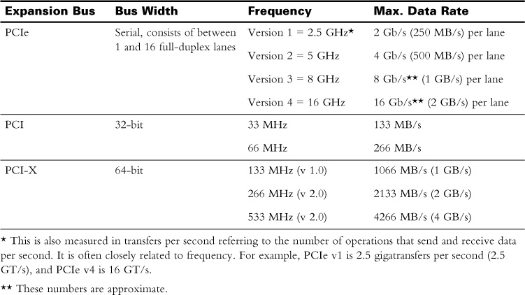
Table 30-3 Expansion Slot Details
Power Connectors
The motherboard needs power to operate. Power in the form of alternating current (AC) is converted to direct current (DC) within the power supply. From there, a main power connector supplies power to the motherboard. The most common form factor, ATX, specifies a 24-pin main power connector. On some older systems, this might be a 20-pin connector. The voltages supplied to the motherboard are +3.3 V, +5 V, +12 V, and –12 V outputs and +5 V standby output.
Component Power Connections
Besides the main power connector, the motherboard has additional power connectors for different purposes:
- SATA—Provides power to hard drives and optical drives
- 6 to 8 pin PCIe—Used to supply power to video cards
- 4 to 8 pin auxiliary—Used to provide power to one or more CPUs
Fan Connectors
The motherboard also has connections to provide power to fans. Although fans can be powered directly from the power supply, when fans are connected to the motherboard, additional functionality and features can be added.
Fan connectors on the motherboard will have between 2 and 4 pins. With more pins comes more functionality:
- 2 pins—The fan runs at maximum speed at all times.
- 3 pins—The fan speed can be adjusted by the BIOS/UEFI or through software.
- 4 pins—The fan speed can be adjusted automatically, usually based on temperature.
Front/Top Panel Connectors
A number of items on the case need to be connected to the motherboard. The type and number of items is dependent on the case and motherboard capabilities. These are some common connections that need to be made:
- Power button—Allows the use of a button to turn the computer on or off
- Power light—Indicates the current power state of the computer
- Reset button—Allows the use of a button to restart the computer without turning it off
- Drive activity lights—Indicates when the storage drive is in operation
- USB—Connects case-mounted USB connectors to the motherboard to connect USB devices easily
- Audio—Connects case-mounted audio jacks such as headphones or microphones
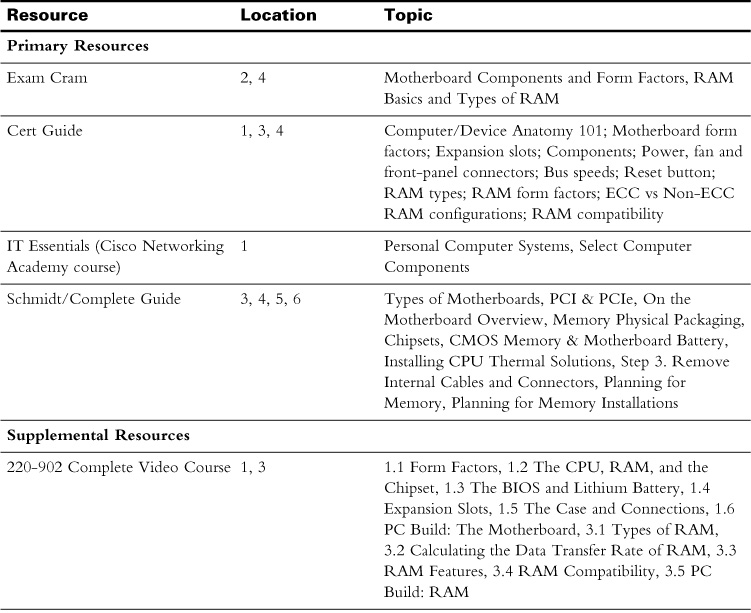
Study Resources
For today’s exam topics, refer to the following resources for more study.
 Check Your Understanding