Day 31. BIOS/UEFI Settings
CompTIA A+ 220-901 Exam Topics
- Objective 1.1: Given a scenario, configure settings and use BIOS/UEFI tools on a PC.
Key Topics
Today’s review focuses on understanding and configuring the options that can be set in the basic input/output system (BIOS). We also will be looking at the new Unified Extensible Firmware Interface (UEFI) system and the tools it provides, including built-in diagnostics, boot sequencing, and hardware component information.
Purpose of the BIOS
The BIOS is software stored on a small, nonvolatile chip on the motherboard. The BIOS program controls the startup process and loads the operating system (OS) into memory. It is used to identify and configure much of the hardware in a computer.
Note
Apple has a BIOS/UEFI, but not like Intel-based machines. Apple systems are designed from the ground up in a unified manner and do not usually require maintenance or device configuration at the hardware level.
Device Support
Any input/output device needs an intermediary between it and the CPU. Two different types of devices are controlled by the BIOS: configurable devices and nonconfigurable devices. Configurable devices include items such as hard drives, RAM, the CPU, and even the expansion slots. Nonconfigurable devices might be items like the battery or the internal speakers.
Virtualization also can be controlled by the BIOS. Because AMD CPUs come with this option turned on, the only time you might need to access the BIOS for changing virtualization is when dealing with an Intel processor.
The BIOS functions outside of the OS, and it is not dependent on it. Most BIOSes will automatically configure a system. If the BIOS is reset, it will return to the factory settings. Moving through the BIOS can be performed with the mouse or by using keys on the keyboard such as the + and – or the Tab keys.
BIOS Configuration Options
Items typically configured in BIOS include some of the following:
- Change boot order
- Change date and time
- Set or change storage devices
- Test and view memory settings
- Change bootup NumLock status
- Enable or disable the power-on self-test (POST)
- Set, change, or remove password access
- Enable or disable CPU cache
- Change CPU or memory settings
- Set or change power settings (ACPI)
- Change voltages
- Enable or disable redundant array of independent disks (RAID), universal serial bus (USB), FireWire, audio, floppy, or serial/parallel ports
Each manufacturer of BIOSes has its own layout and options for the components it covers. Table 31-1 describes the most common BIOS features and settings, although it is not meant to be completely comprehensive.
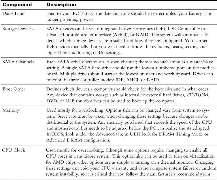
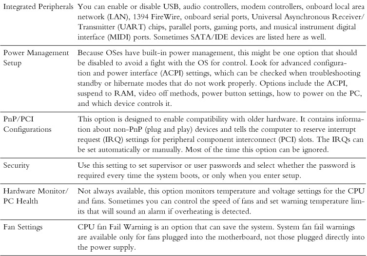
Table 31-1 Common BIOS Features and Settings
Booting with BIOS
BIOS starts and completes the POST, and then it loads the master boot record (MBR) located in the boot sector of the hard disk. Usually located under the Boot tab or on the main menu, the boot order configures whether you use a hard drive, a CD-ROM or DVD drive, a removable device, or a network boot (PXE) through the NIC card to start the OS on a computer, and in what order. Although no longer found on most PCs, floppy drives also can be used to boot a system.
Many technicians will set the boot order to start with the removable devices, such as USB or CD-DVD drives, first to make troubleshooting easier. As long as bootable media is not in those devices, the system will move to the next bootable device on the list, eventually loading the first bootable (active) drive.
Accessing the Physical BIOS
You can access BIOS in a number of ways, mostly by using keyboard shortcuts determined by the manufacturer of the motherboard. Options to reach the BIOS differ between manufacturers. Usually the key sequences are performed during the booting of the computer.
The POST
POST is short for power-on self-test. BIOS loads this diagnostic utility when the computer is first turned on. It then verifies system memory, activates system devices, and locates the boot devices. Control is then passed on to the OS after the system has passed these tests. If any device does not pass the test, BIOS uses a beeping noise (beep codes) to alert the user.
Beep Codes
Beeping codes differ for each BIOS manufacturer. Typical beep codes are described in Table 31-2.
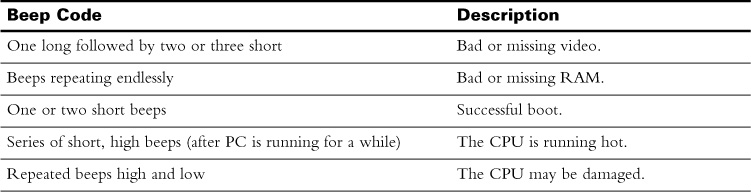
Table 31-2 Typical Beep Codes
 Activity 31-1: Beep Codes
POST Cards
A POST card is a circuit board that fits into an open expansion slot on the motherboard. It uses numeric codes to identify component failure as the computer runs through the boot process. If a display shows 00 or FF after booting, it indicates that the system is probably okay. Any other numeric number will need to be investigated using the accompanying documentation or by accessing the POST card’s website.
Complementary Metal-oxide Semiconductor
The complementary metal-oxide semiconductor (CMOS) is a separate chip on the motherboard. Unlike BIOS, it is actually a volatile, low-power RAM chip powered by a small, watch-type battery (CR2032 cell). It originally stored information about the hardware and contained the system settings, such as boot order for the PC. Most computers still use the CMOS to maintain the system date and time.
The CMOS Battery
The CMOS battery is located on the motherboard. If the battery is removed or goes bad, the system loses the date and time information.
To replace the CMOS battery, take a flat-head screwdriver and lift up on one end of the clip holding the battery in place. After the new battery is in place, reboot the machine, reset any CMOS values, and save the settings.
The Difference Between BIOS and CMOS
The term CMOS is still in use, but nonvolatile storage in today’s PCs is stored in the electrically erasable programmable read-only memory (EEPROM) or flash memory. The only usage for the battery is to keep the real-time clock going. When the battery goes bad, the system date and time will reset to the manufacturer’s installation date. This is the only notification the user will receive. Figure 31-1 shows how the lithium battery communicates with both the CMOS and the battery.
Figure 31-1 BIOS, CMOS, and the Battery
UEFI
BIOS is now considered the older legacy interface for a computer. UEFI is the latest, and although it does the same tasks as BIOS, it is much more efficient and offers more functionality. UEFI is not just a replacement for BIOS, though; it is actually a small operating system with a graphical user interface (GUI) that can access the Internet as well as perform other tasks previously available only after the system has booted into the OS. Figure 31-2 shows an ASUS motherboard’s UEFI BIOS utility.
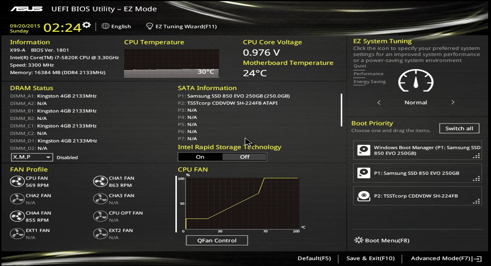
Figure 31-2 UEFI Setup Screen
Purpose of UEFI
UEFI was developed by Intel to deal with newer hardware and make up for restrictions in BIOS. For example, security measures could not be added to the BIOS due to space and functionality limitations. UEFI not only has room for these more useful features, but also can perform faster boots.
UEFI is OS independent, supports multiple extensions, and has its own extensible firmware interface (EFI) shell. In the EFI shell, EFI applications such as Internet access, backup, diagnostics utilities (instead of beep codes), and malware scanners can be run. It contains its own boot loader that executes the OS boot loader.
Accessing UEFI
Access to the UEFI is through special manufacturer-specific keystrokes performed during bootup. Although it is faster to just reboot the system and use the correct key sequence to get into setup, with UEFI, access is also possible from the OS. In Windows 8 and later, press the Windows key+C to access Charms. Select the Settings charm, and then click Change PC Settings. Select Update & Recovery and then Restart Now. When prompted to Choose an Option, select Troubleshoot. Under the Advanced option, select UEFI Firmware Settings, and then select Restart. This will take the system to the UEFI screen.
Advantages of UEFI over BIOS
Using UEFI is more advantageous than BIOS in the following ways:
- It can handle a larger partition and disk size (up to 2.2 TB).
- It can enhance the boot time and speed of the computer, including resuming from the hibernation state.
- UEFI can allow only authentic drivers and services to load, whereas BIOS is susceptible to malware, especially rootkits.
- BIOS is difficult to update, whereas UEFI offers access to the Internet.
- UEFI can access all PC hardware in both 32-bit and 64-bit versions.
- UEFI offers a more easy-to-read interface and can be backed up or stored on a disk or even on a network drive.
- UEFI can be backward compatible with BIOS settings controlling UEFI hardware.
- UEFI offers support for 64-bit drivers, which the system can use to address more than 17.2 billion GB of RAM.
Booting with UEFI
With BIOS, the boot is all about the very start of the disk that contains a small piece of code it knows how to execute. BIOS knows nothing beyond that. UEFI not only defines a common format for code that can be executed, but also is capable of reading a file system.
One of the best features of UEFI is how it works with storage and boots up a system. BIOS limitations required the creation and use of the MBR, a 32-bit table used to save information about hard drive data. The MBR also limits physical partitions to only four, each of which can be up to only 2 TB in size. In comparison, UEFI uses the GUID partition table (GPT), which supports 128 partitions that can be up to 1 ZB in size. (Both are also restricted by limitations in the OS used.)
Instead of a MBR, the UEFI is aware of the file systems loaded on the computer—it even has its own file system. Booting with a UEFI system assumes the use of a GPT. Data critical to operation is located in each partition, and GPT disks have backup partition tables for redundancy. GPT disks use version number and size fields for future expansion. Figure 31-3 displays the Boot tab of a typical UEFI utility.
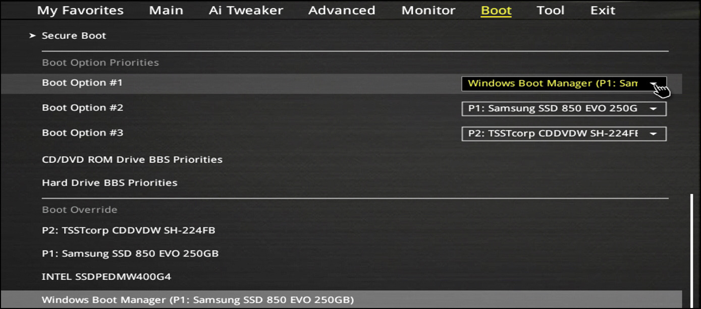
Figure 31-3 Boot Order UEFI
Firmware Upgrades
Both the BIOS and UEFI are considered firmware. Firmware is permanent software that has been written to the read-only memory (ROM) of a device. To upgrade firmware with a newer version, follow the procedures created by the motherboard or device manufacturer.
Updating BIOS is called flashing. Booting to a bootable device that holds a small upgrade utility is common. To update the BIOS, the older software must be completely erased.
Losing power or using an incorrect update during a flash upgrade can be fatal to your motherboard. Make sure the upgrade is needed by identifying the current version before beginning. Double-check that the correct upgrade is being used by reviewing the manufacturer’s website, watching the boot process, or going into setup and identifying the version on the BIOS screen.
Boot Security Measures
The following options can provide security at the firmware level:
- Passwords—A system administrator and a user-level password can be set on most BIOSes and UEFI to protect access to the computer before the OS is loaded.
- Secure Boot—A standard that has been adopted by many motherboard manufacturers, it is designed to check the integrity of system files before allowing the boot process to complete.
- LoJack—A product made by Absolute Software, it enables the remote locating, locking, and deleting of data on mobile devices.
- Trusted Platform Module (TPM)—A chip that is on the motherboard, it provides RSA encryption keys specific to the PC for hardware authentication.
- Dual-BIOS—To avoid motherboard failure, a main BIOS chip and a backup BIOS chip can be installed on the motherboard. If the first chip fails, the second chip will be used.
- Case Open Feature/Reset—Works with a sensor to detect whether the case has been opened.
- Temperature Alarms—Set warnings or actions when a CPU or chipset reaches a specified temperature (beeps, shutdown).
Activity 31-2: UEFI or BIOS
Activity 31-3: Understanding the Terminology
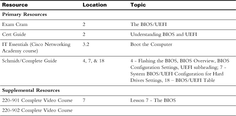
Study Resources
For today’s exam topics, refer to the following resources for more study.
 Check Your Understanding