Day 29. WAN Technologies
CompTIA Network+ N10-006 Exam Topics
- 1.4 Explain the characteristics and benefits of various WAN technologies
Key Topics
First today, we review packet switching and circuit switching. Then we review all the various ways networks are connected together through WAN technologies.
Packet Switching and Circuit Switching
The switching function provides communication pathways between two endpoints and manages how data flows between them. The two most common switching methods are circuit switching and packet switching.
Integrated Service Digital Network (ISDN), shown in Figure 29-1, is an example of a circuit-switched network.
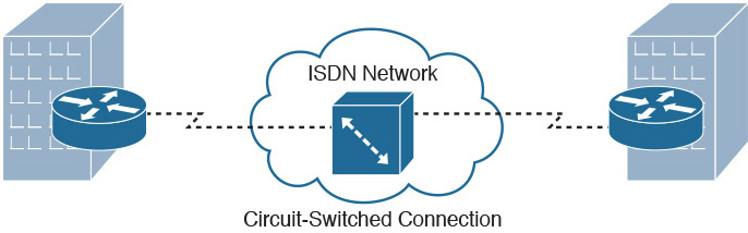
Figure 29-1 Circuit Switching ISDN Topology
Circuit switching requires a dedicated physical connection between the sending and receiving devices. For example, parties involved in a phone call have a dedicated link between them for the duration of the conversation. When either party disconnects, the circuit is broken, and the data path is lost. This is an accurate representation of how circuit switching works with network and data transmissions. The sending system establishes a physical connection, and the data is transmitted between the two. When the transmission is complete, the channel is closed.
A Frame Relay network, shown in Figure 29-2, is an example of a packet-switched network.
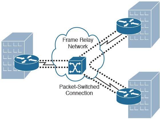
Figure 29-2 Packet Switching Frame Relay Topology
In packet switching, messages are broken into smaller pieces called packets. Each packet is assigned source and destination addresses. Packets are required to have this information because they do not always use the same path or route to get to their intended destination. Packets can take an alternative route if a particular route is unavailable for some reason.
Table 29-1 compares circuit switching and packet switching.
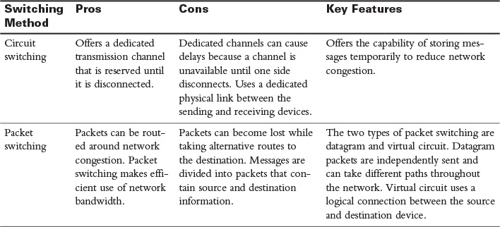
Table 29-1 Circuit Switching and Packet Switching Comparison
WAN Link Options
A variety of different methods can be used to link networks together. To select an appropriate WAN technology, you need the ability to compare one WAN technology to another.
Home and Small Office
Home and small office networks can connect to other networks and the Internet through a variety of methods.
Dialup
Dialup connectivity is done through the Public Switched Telephone Network (PSTN), which is composed of multiple telephone carriers from around the world. Although the bandwidth available on the PSTN is limited, it is more likely to be available in a given location than other wired WAN solutions. A dialup connection can be used to access the Internet by connecting a computer to a modem, connecting the modem to an analog phone line, and dialing in to a service provider. The service provider can then connect to the Internet, as shown in Figure 29-3. Modems in the United States and Canada are limited to 53.3Kbps download and 48.0Kbps upload.
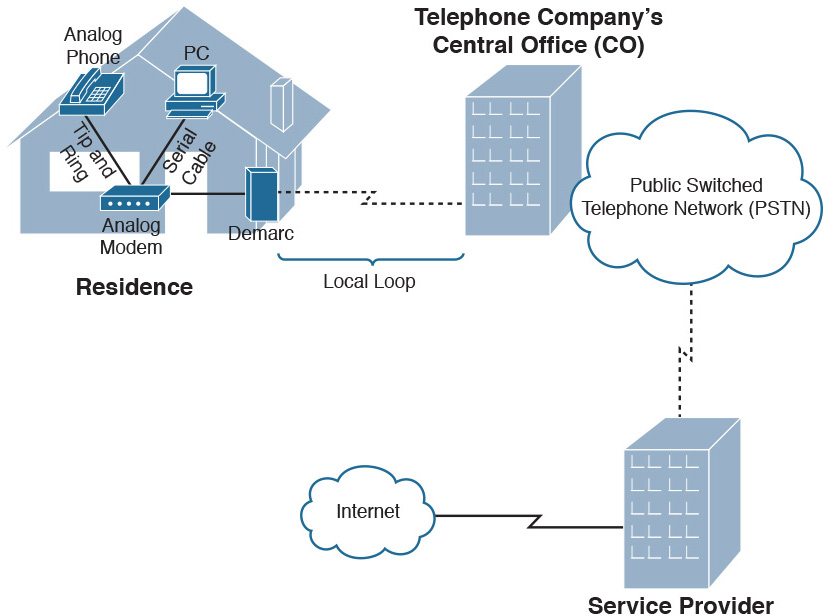
Figure 29-3 PSTN Dialup Topology
Table 29-2 describes some of the common terminology used to describe PSTNs.
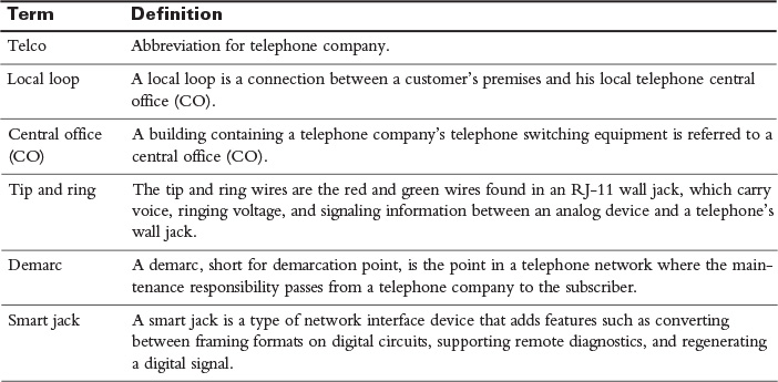
Table 29-2 Common PSTN Terms
ISDN
ISDN connections are considerably faster than regular modem connections. ISDN is a digital technology that supports multiple 64Kbps channels on a single connection. ISDN circuits are classified as either a basic rate interface (BRI) circuit or a primary rate interface (PRI) circuit:
- BRI—A BRI circuit consists of two 64Kbps bearer (B) channels and one 16Kbps delta (D) channel. The B channels carry voice, video, and data. They can carry two separate voice conversations or they can be combined using PPP multilink. The D channel carries Layer 2 (Q.921) and Layer 3 (Q.931) signaling.
- PRI—A PRI circuit is equivalent to a 1.544Mbps T1 circuit. Therefore, it consists of 23 B channels and one 64Kbps D channel.
The components of an ISDN network are shown in Figure 29-4.
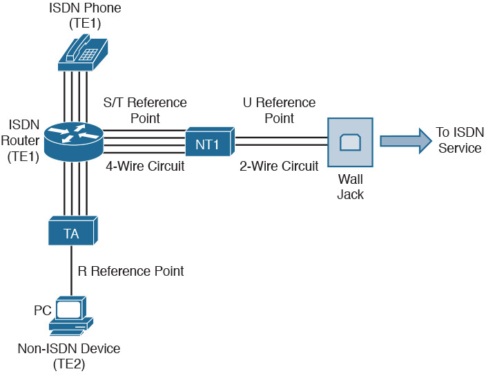
Figure 29-4 ISDN Topology
Table 29-3 lists a brief description of the ISDN components shown in Figure 29-4.
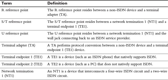
Table 29-3 ISDN Components
DSL
Digital Subscriber Line (DSL) is a group of technologies that provide high-speed data transmission over existing telephone wiring. There are many different varieties of DSL. Together, all these variations are referred to as xDSL. Popular variants include the following:
- Asymmetric DSL (ADSL)—ADSL is the most popular variant. It include a channel for analog voice conversations, a channel for uploads, and a channel for downloads. It is called asymmetrical because the download channel is faster than the upload channel.
- Symmetric DSL (SDSL)—SDSL is more suited to business applications because it offers the same speeds for uploads and downloads.
- Very High Bit-Rate DSL (VDSL)—VDSL is a variant of ADSL that provides data speeds of up to 13Mbps.
Table 29-4 summarizes the maximum speeds for all the DSL variants.
Table 29-4 DSL Speeds
PPP
Point-to-Point Protocol (PPP) is a common Layer 2 protocol used on dedicated leased lines. It can carry multiple Layer 3 protocols, such as IPv4 and IPv6. IP uses PPP’s IP control protocol (IPCP). When a link is configured with IP and PPP, IPCP initiates the Link Control Protocol (LCP), which can provide any or all of the following features:
- Multilink interface—PPP multilink allows multiple interfaces to be combined into one logical interface.
- Looped link detection—A Layer 2 loop (of PPP links) can be detected and prevented.
- Error detection—Frames containing errors can be detected and discarded by PPP.
- Authentication—PPP provides three methods of authentication methods:
- Password Authentication Protocol (PAP)—PAP performs one-way authentication. Passwords are sent in clear text.
- Challenge Handshake Authentication Protocol (CHAP)—CHAP performs one-way authentication using a three-way handshake (challenge, response, and acceptance). Passwords are not sent across the link.
- Microsoft Challenge Handshake Authentication Protocol (MS-CHAP)—MS-CHAP is a Microsoft-enhanced version of CHAP, offering a collection of additional features, including two-way authentication.
Broadband Cable
Broadband cable is an always-on Internet access method available in areas that have digital cable television. Connectivity is achieved by using a device called a cable modem. It has a coaxial connection for connecting to the provider’s outlet and an unshielded twisted-pair (UTP) connection for connecting directly to a system or to a hub, switch, or router.
The provider’s infrastructure probably has a mix of coaxial and fiber cabling called hybrid fiber-coax (HFC). A broadband cable network is shown in Figure 29-5.
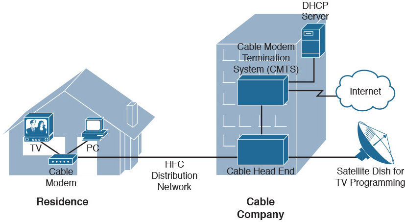
Figure 29-5 Broadband Cable Topology
Wireless
Wireless WAN connection options include satellite, Worldwide Interoperability for Microwave Access (WiMAX), and several varieties of cellular technologies.
Satellite
Some locations do not have the WAN connectivity options, such as DSL connections or cable modems, commonly available in urban areas. However, these locations might be able to connect to the Internet or to a remote office using satellite communications, where a transmission is bounced off of a satellite, received by a satellite ground station, and then sent to its destination using either another satellite hop or a wired WAN connection.
Two different types of broadband Internet satellite services are deployed:
- One-way satellite system—A one-way satellite system requires a satellite card and a satellite dish installed at the end user’s site. Outgoing requests are sent using a phone line. Inbound traffic returns on the satellite link.
- Two-way satellite system—A two-way satellite system, in contrast, provides data paths for both upstream and downstream data. Bidirectional communication occurs directly between the end user’s site and the satellite.
WiMAX
WiMAX (Worldwide Interoperability for Microwave Access) provides wireless Internet broadband access to fixed locations (as an alternative to technologies such as DSL or cable). Depending on the WiMAX service provider, WiMAX coverage areas could encompass entire cities or small countries. Based on the IEEE 802.16 standard, WiMAX can provide data rates up to 1Gbps. Although WiMAX can send data up to 31 miles (50 km), it is most effective within one mile. WiMAX is a popular choice for connecting cell towers in cellular networks.
Cellular Technologies
Some cellular phone technologies (for example, Long-Term Evolution [LTE], which supports a 100Mbps data rate to mobile devices and a 1Gbps data rate for stationary devices) can be used to connect a mobile device (such as a smartphone) to the Internet. Other technologies for cellular phones include the older 2G edge, which provides slow data rates. 2G edge was improved upon with 3G, in addition to the newer 4G, LTE, and Evolved High-Speed Packet Access (HSPA+). Code division multiple access (CDMA) and Global System for Mobile Communications (GSM) are the two major radio systems used in cell phones.
SONET
Synchronous Optical Network (SONET) is a fiber-optic WAN technology that delivers voice, data, and video at speeds starting at 51.84Mbps. SONET uses dense wavelength-division multiplexing (DWDM), which uses erbium-doped fiber amplifiers (EDFA) to amplify the signal and allow it to travel greater distances. An alternative to DWDM is CWDM (coarse wavelength-division multiplexing), which is commonly used with television cable networks. SONET is classified into various Optical Carrier (OCx) levels, as shown in Table 29-5.
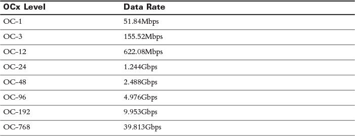
Table 29-5 Optical Carrier Data Rates
SONET can connect as many as 16 other devices in a linear fashion (similar to a bus topology) or in a ring topology. A metropolitan area network (MAN), as depicted in Figure 29-6, often uses SONET in a ring topology.
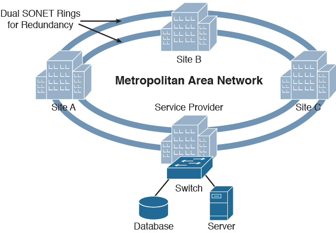
Figure 29-6 SONET Ring Topology
Dedicated Leased Lines
A dedicated leased line is typically a point-to-point digital circuit interconnecting two sites. All the bandwidth on that circuit is available to those sites. These circuits can use multiplexing technology to simultaneously carry multiple conversations in different 64Kbps channels. A single 64Kbps channel is called a Digital Signal 0 (DS0). WAN technologies commonly used with dedicated leased lines include the following:
- T1—T1 circuits were originally used in telephony networks, with the intent of one voice conversation being carried in a single channel. A T1 circuit is composed of 24 DS0s, which is called a Digital Signal 1 (DS1). The bandwidth of a T1 circuit is 1.544Mbps.
- T3—T3 circuits combine 672 DS0s into a single physical connection, which is called a Digital Signal 3 (DS3). A T3 circuit has a bandwidth capacity of 44.7Mbps.
- E1—E1 circuits are popular outside of North America and Japan. They contain 32 channels, in contrast to the 24 channels on a T1 circuit, for a bandwidth capacity of 2.048Mbps.
- E3—E3 circuits have a bandwidth capacity of 34.4Mbps, which is less than a T3 circuit.
Dedicated leased lines are terminated at the customer’s premises with a channel service unit/data service unit (CSU/DSU), as shown in Figure 29-7.
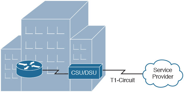
Figure 29-7 Terminating a Leased Line
Enterprise WANs
Initially, dedicated leased lines were used by enterprises to connect various sites. However, as network traffic and the number of required WAN connections grew, leased lines became cost prohibitive. Several technologies emerged to answer the need, including Frame Relay, Asynchronous Transfer Mode (ATM), Multiprotocol Label Switching (MPLS), and Metro Ethernet.
Frame Relay
Frame Relay sites are interconnected using virtual circuits (VCs). Frame Relay is a Layer 2 technology that uses locally significant identifiers called data-link connection identifiers (DLCI). DLCIs identify the VC. A single router interface can have multiple VCs, as shown in Figure 29-8.
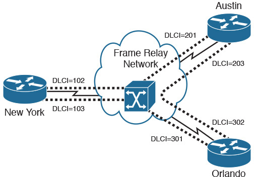
Figure 29-8 Frame Relay Topology
Unlike a dedicated leased line, Frame Relay shares a service provider’s bandwidth with other customers of its service provider. Therefore, subscribers might purchase a service level agreement (SLA) to guarantee a minimum level of service. Part of the Frame Relay SLA would be a minimum bandwidth guarantee called a committed information rate (CIR).
During times of congestion, the service provider manages transmission rates using the backward explicit congestion notification (BECN) and forward explicit congestion notification (FECN) bits in the frame relay header. The BECN and FECN bits inform the customers to slow down the transmission rates.
If the service is not congested, a customer might have an SLA that allows transmission rates higher than the CIR. In such cases, the discard eligibility (DE) bit is set in each frame. If the service becomes congested, these frames can be discarded by the Frame Relay service provider.
ATM
ATM is a Layer 2 technology that uses VCs. However, ATM uses a fixed-length frame, called a cell, which includes 48 bytes of data and a 5-byte header, as shown in Figure 29-9.
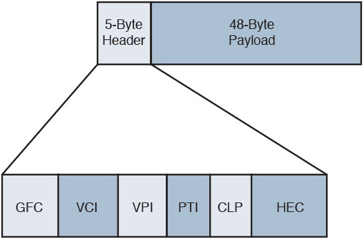
Figure 29-9 ATM Cell Format
Table 29-6 details the fields of the ATM cell header.
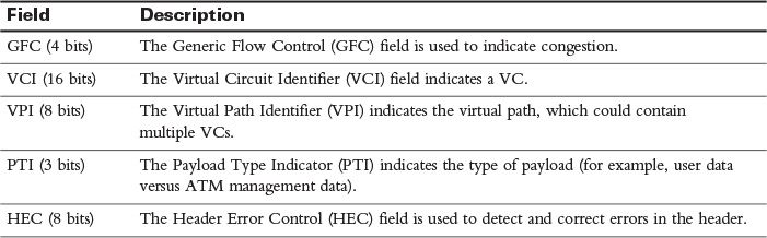
Table 29-6 ATM Header Fields
ATM VCs are identified with a VPI/VCI pair, as shown in Figure 29-10.
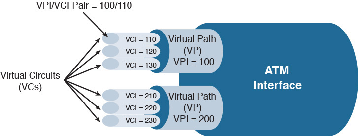
Figure 29-10 Identifying ATM VCs
MPLS
Multiprotocol Label Switching (MPLS) can accommodate both Frame Relay and ATM on the same backbone. It does this by inserting a 32-bit header between the Layer 2 and Layer 3 headers. The 32-bit header contains a 20-bit label. This label is used to make forwarding decisions within an MPLS cloud. Therefore, the process of routing MPLS frames through an MPLS cloud is commonly referred to as label switching. Figure 29-11 shows an MPLS topology.
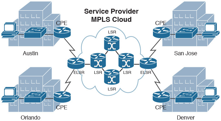
Figure 29-11 MPLS Topology
Table 29-7 lists the definitions for the components of the MPLS topology shown in Figure 29-11.
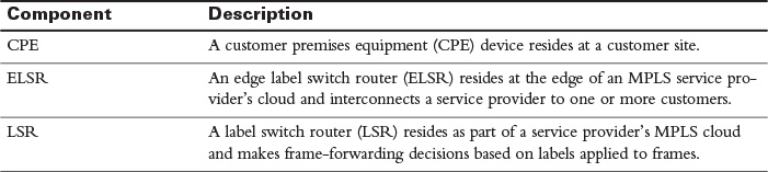
Table 29-7 MPLS Components
Metro Ethernet
Metro Ethernet is simply Ethernet technology extended into the metropolitan area network (MAN). The customer connects to the service provider through an Ethernet connection (using an RJ-45 connector). This effectively extends the LAN into the MAN. The service provider is responsible for configuring the logical connections between the customer sites. The technologies used with the service provider network are hidden from the customer.
 Video 29.1—WAN Links (Circuit Switched)
Video 29.2—WAN Links (Packet Switched)
 Activity: Identify the WAN Technology
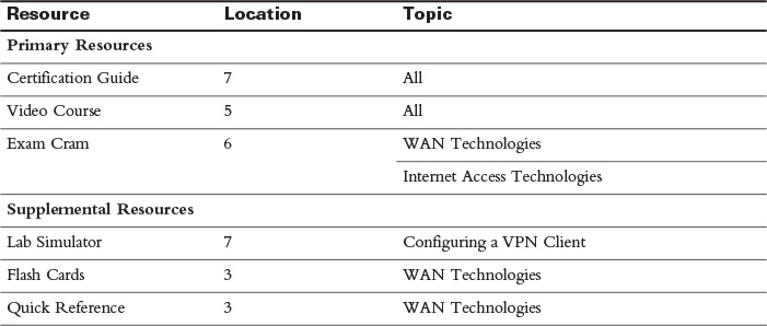
Study Resources
For today’s exam topics, refer to the following resources for more study.
 Check Your Understanding