Day 31. Networking Models, Devices, and Components
CCNA 200-125 Exam Topics
- Compare and contrast OSI and TCP/IP models
- Compare and contrast TCP and UDP protocols
- Describe the impact of infrastructure components in an enterprise network
- Compare and contrast collapsed core and three-tier architectures
- Compare and contrast network topologies
- Select the appropriate cabling type based on implementation requirements
Key Points
Both the Open Systems Interconnection (OSI) and Transmission Control Protocol/Internet Protocol (TCP/IP) networking models are important conceptual frameworks for understanding networks. Today we review the layers and functions of each model, along with the process of data flow from source to destination. We also spend some time on the Transmission Control Protocol (TCP) and the User Datagram Protocol (UDP). Then we wrap up the day with a look at devices used in today’s networks, the media used to interconnect those devices, and the different types of network topologies.
Note:
This day might seem a bit long. However, you need to be very familiar with all of this content. Scan the day, focusing on areas where you feel less confident in your knowledge.
The OSI and TCP/IP Models
To understand how communication occurs across the network, you can use layered models as a framework for representing and explaining networking concepts and technologies. Layered models, such as the TCP/IP and OSI models, support interoperability between competing vendor product lines.
The OSI model principally serves as a tool for explaining networking concepts and troubleshooting. However, the protocols of the TCP/IP suite are the rules by which networks now operate. Because both models are important, you should be well versed in each model’s layers and know how the models map to each other. Figure 31-1 summarizes the two models.
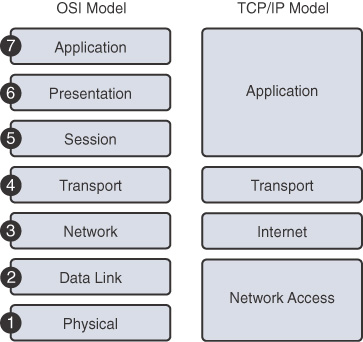
Figure 31-1 OSI and TCP/IP Models
Using two models can be confusing; however, these simple guidelines might help:
- When discussing layers of a model, we are usually referring to the OSI model.
- When discussing protocols, we are usually referring to the TCP/IP model.
The next sections quickly review the OSI layers and the TCP/IP protocols.
OSI Layers
Table 31-1 summarizes the layers of the OSI model and provides a brief functional description.
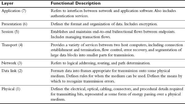
Table 31-1 OSI Model Layers and Functions
The following mnemonic phrase, in which the first letter represents the layer (A stands for Application), can help in memorizing the name and order of the layers from top to bottom:
All People Seem To Need Data Processing
TCP/IP Layers and Protocols
The TCP/IP model defines four categories of functions that must occur for communications to succeed. Most protocol models describe a vendor-specific protocol stack. However, because the TCP/IP model is an open standard, one company does not control the definition of the model.
Table 31-2 summarizes the TCP/IP layers, their functions, and the most common protocols.
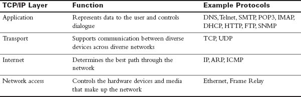
Table 31-2 TCP/IP Layer Functions
In the coming days, we review these protocols in more detail. For now, a brief description of the main TCP/IP protocols follows:
- Domain Name System (DNS): Provides the IP address of a website or domain name so that a host can connect to it
- Telnet: Enables administrators to log in to a host from a remote location
- Simple Mail Transfer Protocol (SMTP), Post Office Protocol (POP3), and Internet Message Access Protocol (IMAP): Facilitates sending email messages between clients and servers
- Dynamic Host Configuration Protocol (DHCP): Assigns IP addressing to requesting clients
- Hypertext Transfer Protocol (HTTP): Transfers information between web clients and web servers
- File Transfer Protocol (FTP): Facilitates the download and upload of files between an FTP client and FTP server
- Simple Network Management Protocol (SNMP): Enables network management systems to monitor devices attached to the network
- Transmission Control Protocol (TCP): Supports virtual connections between hosts on the network to provide reliable delivery of data
- User Datagram Protocol (UDP): Supports faster, unreliable delivery of lightweight or time-sensitive data
- Internet Protocol (IP): Provides a unique global address to computers for communicating over the network
- Address Resolution Protocol (ARP): Finds a host’s hardware address when only the IP address is known
- Internet Control Message Protocol (ICMP): Sends error and control messages, including reachability to another host and availability of services
- Ethernet: Serves as the most popular LAN standard for framing and preparing data for transmission onto the media
 Activity: Order the Layers of the OSI and TCP/IP Models
Protocol Data Units and Encapsulation
As application data is passed down the protocol stack on its way to be transmitted across the network media, various protocols add information to it at each level. This is commonly known as the encapsulation process. The data structure at any given layer is called a protocol data unit (PDU). Table 31-3 lists the PDUs at each layer of the OSI model.
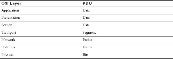
Table 31-3 PDUs at Each Layer of the OSI Model
The following steps summarize the communication process from any source to any destination:
1. Data is created at the application layer of the originating source device.
2. As the data passes down the protocol stack in the source device, it is segmented and encapsulated.
3. The data is generated onto the media at the network access layer of the stack.
4. The data is transported through the internetwork, which consists of media and any intermediary devices.
5. The destination device receives the data at the network access layer.
6. As the data passes up the stack in the destination device, it is decapsulated and reassembled.
7. The data is passed to the destination application at the application layer of the destination device.
The TCP/IP Application Layer
The application layer of the TCP/IP model provides an interface between software such as a web browser and the network itself. The process of requesting and receiving a web page works like this:
1. An HTTP request is sent, including an instruction to “get” a file (which is often a website’s home page).
2. An HTTP response is sent from the web server with a code in the header, usually either 200 (request succeeded and information is returned in response) or 404 (page not found).
The HTTP request and the HTTP response are encapsulated in headers. The content of the headers allows the application layers on each end device to communicate. Regardless of the application layer protocol (HTTP, FTP, DNS, and so on), all use the same general process for communicating between application layers on the end devices.
The TCP/IP Transport Layer
The transport layer, through TCP, provides a mechanism to guarantee delivery of data across the network. TCP supports error recovery to the application layer through the use of basic acknowledgment logic. Adding to the process for requesting a web page, TCP operation works like this:
1. The web client sends an HTTP request for a specific web server down to the transport layer.
2. TCP encapsulates the HTTP request with a TCP header and includes the destination port number for HTTP.
3. Lower layers process and send the request to the web server.
4. The web server receives HTTP requests and sends a TCP acknowledgment back to the requesting web client.
5. The web server sends the HTTP response down to the transport layer.
6. TCP encapsulates the HTTP data with a TCP header.
7. Lower layers process and send the response to the requesting web client.
8. The requesting web client sends an acknowledgment back to the web server.
If data is lost at any point during this process, TCP must recover the data. HTTP at the application layer does not get involved in error recovery.
In addition to TCP, the transport layer provides UDP, a connectionless, unreliable protocol for sending data that does not require or need error recovery. Table 31-4 lists the main features that the transport protocols support. Both TCP and UDP support the first function; only TCP supports the rest.
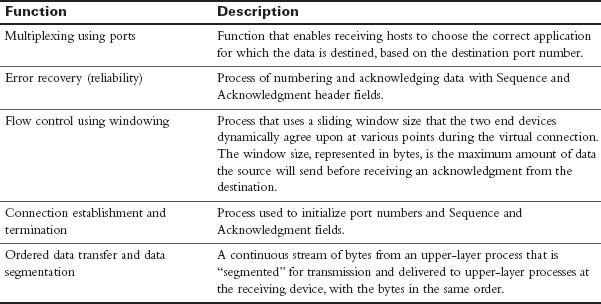
Table 31-4 TCP/IP Transport Layer Features
TCP Header
TCP provides error recovery, but to do so, it consumes more bandwidth and uses more processing cycles than UDP. TCP and UDP rely on IP for end-to-end delivery. TCP is concerned with providing services to the applications of the sending and receiving computers. To provide all these services, TCP uses a variety of fields in its header (see Figure 31-2).
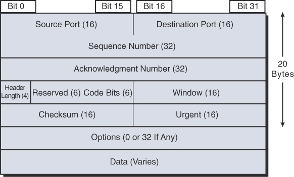
Figure 31-2 TCP Header
Port Numbers
The first two fields of the TCP header—the source and destination ports—are also part of the UDP header that appears later in Figure 31-7. Port numbers provide TCP (and UDP) with a way to multiplex multiple applications on the same computer. Web browsers now support multiple tabs or pages. Each time you open a new tab and request another web page, TCP assigns a different source port number and sometimes multiple port numbers. For example, you might have five web pages open. TCP almost always assigns destination port 80 for all five sessions. However, the source port for each is different. This is how TCP (and UDP) multiplexes the conversation so that the web browser knows in which tab to display the data.
TCP and UDP usually dynamically assign the source ports, starting at 1024 up to a maximum of 65535. Port numbers below 1024 are reserved for well-known applications. Table 31-5 lists several popular applications and their well-known port numbers.
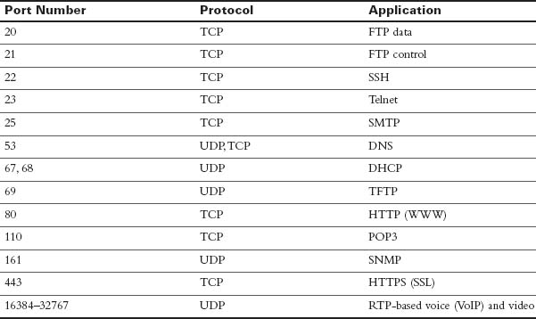
Table 31-5 Popular Applications and Their Well-Known Port Numbers
Error Recovery
Also known as reliability, TCP provides error recovery during data transfer sessions between two end devices that have established a connection. The Sequence and Acknowledgment fields in the TCP header track every byte of data transfer and ensure that missing bytes are retransmitted.
In Figure 31-3, the Acknowledgment field sent by the web client (4000) implies the next byte to be received; this is called positive acknowledgment.
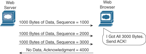
Figure 31-3 TCP Acknowledgment Without Errors
Figure 31-4 depicts the same scenario, except now with some errors. The second TCP segment was lost in transmission. Therefore, the web client replies with an ACK field set to 2000. This is called a positive acknowledgment with retransmission (PAR) because the web client is requesting that some of the data be retransmitted. The web server will now resend data starting at segment 2000. In this way, lost data is recovered.
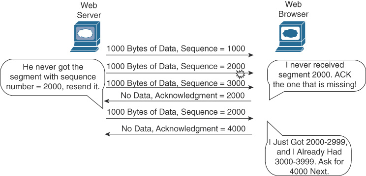
Figure 31-4 TCP Acknowledgment with Errors
Although not shown, the web server also sets a retransmission timer and awaits acknowledgment, just in case the acknowledgment is lost or all transmitted segments are lost. If that timer expires, the web server sends all segments again.
Flow Control
TCP handles flow control through a process called windowing. The two end devices negotiate the window size when initially establishing the connection; then they dynamically renegotiate window size during the life of the connection, increasing its size until it reaches the maximum window size of 65,535 bytes or until errors occur. Window size is specified in the Window field of the TCP header. After sending the amount of data specified in the window size, the source must receive an acknowledgment before sending the next window size of data.
Connection Establishment and Termination
Connection establishment is the process of initializing sequence and acknowledgment fields and agreeing on port numbers and window size. The three-way connection establishment phase shown in Figure 31-5 must occur before data transfer can proceed.
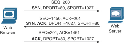
Figure 31-5 TCP Connection Establishment
In the figure, DPORT and SPORT are the destination and source ports. SEQ is the sequence number. In bold are SYN and ACK, with each representing a 1-bit flag in the TCP header used to signal connection establishment. TCP initializes the Sequence Number and Acknowledgment Number fields to any number that fits into the 4-byte fields. The initial Sequence Number is a random 32-bit number generated with each new transmission. The Acknowledgment Number is received back and increments the sender’s sequence number by 1.
When data transfer is complete, a four-way termination sequence occurs that uses an additional flag, called the FIN bit (see Figure 31-6).
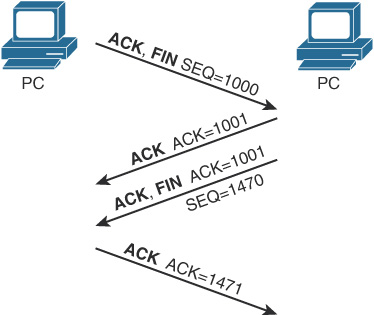
Figure 31-6 TCP Connection Termination
UDP
TCP establishes and terminates connections between endpoints, whereas UDP does not. Therefore, UDP is called a connectionless protocol. It provides no reliability, no windowing, and no reordering of the data. However, UDP does provide data transfer and multiplexing using port numbers, and it does so with fewer bytes of overhead and less processing than TCP. Applications that use UDP can trade the possibility of some data loss for less delay, such as VoIP. Figure 31-7 compares the two headers.
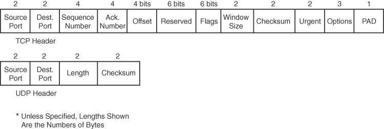
Figure 31-7 TCP and UDP Headers
Activity: Identify the TCP and UDP Characteristics
The TCP/IP Internet Layer
The Internet layer of the TCP/IP model and its Internet Protocol (IP) define addresses so that each host computer can have a different IP address. In addition, the Internet layer defines the process of routing so that routers can determine the best path to send packets to the destination. Continuing with the web page example, IP addresses the data as it passes from the transport layer to the Internet layer:
1. The web client sends an HTTP request.
2. TCP encapsulates the HTTP request.
3. IP encapsulates the transport segment into a packet, adding source and destination addresses.
4. Lower layers process and send the request to the web server.
5. The web server receives HTTP requests and sends a TCP acknowledgment back to the requesting web client.
6. The web server sends the HTTP response down to the transport layer.
7. TCP encapsulates the HTTP data.
8. IP encapsulates the transport segment into a packet, adding source and destination addresses.
9. Lower layers process and send the response to the requesting web client.
10. The requesting web client sends an acknowledgment back to the web server.
The operation of IP includes not only addressing, but also the process of routing the data from source to destination. IP is further discussed and reviewed in the upcoming days.
The TCP/IP Network Access Layer
IP depends on the network access layer to deliver IP packets across a physical network. Therefore, the network access layer defines the protocols and hardware required to deliver data across some physical network by specifying exactly how to physically connect a networked device to the physical media over which data can be transmitted.
The network access layer includes many protocols to deal with the different types of media that data can cross on its way from source device to destination device. For example, data might need to travel first on an Ethernet link and then cross a Point-to-Point (PPP) link, then a Frame Relay link, then a Multiprotocol Label Switching (MPLS) link, and then finally an Ethernet link to reach the destination. At each transition from one media type to another, the network access layer provides the protocols, cabling standards, headers, and trailers to send data across the physical network.
Many times, a local link address is needed to transfer data from one hop to the next. For example, in an Ethernet LAN, Media Access Control (MAC) addresses are used between the sending device and its local gateway router. At the gateway router (depending on the needs of the outbound interface), the Ethernet header might be replaced with an MPLS label. The label serves the same purpose as MAC addresses in Ethernet: to get the data across the link from one hop to the next so that the data can continue its journey to the destination. Some protocols, such as PPP, do not need a link address because only one other device on the link can receive the data.
With the network access layer, we can now finalize our web page example. The following greatly simplifies and summarizes the process of requesting and sending a web page:
1. The web client sends an HTTP request.
2. TCP encapsulates the HTTP request.
3. IP encapsulates the transport segment into a packet, adding source and destination addresses.
4. The network access layer encapsulates the packet in a frame, addressing it for the local link.
5. The network access layer sends the frame as bits on the media.
6. Intermediary devices process the bits at the network access and Internet layers and then forward the data toward the destination.
7. The web server receives the bits on the physical interface and sends them up through the network access and Internet layers.
8. The web server sends a TCP acknowledgment back to the requesting web client.
9. The web server sends the HTTP response down to the transport layer.
10. TCP encapsulates the HTTP data.
11. IP encapsulates the transport segment into a packet, adding source and destination addresses.
12. The network access layer encapsulates the packet in a frame, addressing it for the local link.
13. The network access layer sends the frame as bits on the media.
14. Lower layers process and send the response to the requesting web client.
15. The response travels back to the source over multiple data links.
16. The requesting web client receives the response on the physical interface and sends the data up through the network access and Internet layers.
17. The requesting web client sends a TCP acknowledgment back to the web server.
18. The web page is displayed in the requesting device’s browser.
Data Encapsulation Summary
Each layer of the TCP/IP model adds its own header information. As the data travels down through the layers, it is encapsulated with a new header. At the network access layer, a trailer is also added. This encapsulation process is described in five steps:
Step 1. Create and encapsulate the application data with any required application layer headers. For example, the HTTP OK message can be returned in an HTTP header, followed by part of the contents of a web page.
Step 2. Encapsulate the data supplied by the application layer inside a transport layer header. For end-user applications, a TCP or UDP header is typically used.
Step 3. Encapsulate the data supplied by the transport layer inside an Internet layer (IP) header. IP is the only protocol available in the TCP/IP network model at the Internet layer.
Step 4. Encapsulate the data supplied by the Internet layer inside a network access layer header and trailer. This is the only layer that uses both a header and a trailer.
Step 5. Transmit the bits. The physical layer encodes a signal onto the medium to transmit the frame.
The numbers in Figure 31-8 correspond to the five steps in the list, graphically showing the same encapsulation process.
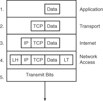
Figure 31-8 Five Steps of Data Encapsulation
Note:
The letters LH and LT stand for link header and link trailer, respectively, and refer to the data link layer header and trailer.
Devices
In today’s wired networks, switches are almost exclusively used to connect end devices to a single LAN. Occasionally, you might see a hub connecting end devices, but hubs are really legacy devices. The following describes the difference between a hub and a switch:
- Hubs were typically chosen as an intermediary device within a very small LAN, in which bandwidth usage was not an issue or cost limitations were a factor. In today’s networks, switches have replaced hubs.
- Switches replaced hubs as the local-area network (LAN) intermediary device because a switch can segment collision domains and provide enhanced security.
Switches
When choosing a switch, these are the main factors to consider:
- Cost: The cost is determined by the number and type of ports, network management capabilities, embedded security technologies, and optional advanced switching technologies.
- Interface characteristics: The number of ports must be sufficient both for now and for future expansion. Other characteristics include uplink speeds, a mixture of UTP and fiber, and modularity.
- Hierarchical network layer: Switches at the access layer have different requirements than switches at the distribution or core layers.
Access Layer Switches
Access layer switches facilitate the connection of end devices to the network. Features of access layer switches include the following:
- Port security
- VLANs
- Fast Ethernet/Gigabit Ethernet
- Power over Ethernet (PoE)
- Link aggregation
- Quality of service (QoS)
Distribution Layer Switches
Distribution layer switches receive the data from the access layer switches and forward it to the core layer switches. Features of distribution layer switches include the following:
- Layer 3 support
- High forwarding rate
- Gigabit Ethernet/10 Gigabit Ethernet
- Redundant components
- Security policies/access control lists
- Link aggregation
- QoS
Core Layer Switches
Core layer switches make up the backbone and are responsible for handling the majority of data on a switched LAN. Features of core layer switches include the following:
- Layer 3 support
- Very high forwarding rate
- Gigabit Ethernet/10 Gigabit Ethernet
- Redundant components
- Link aggregation
- QoS
Routers
Routers are the primary devices used to interconnect networks—LANs, WANs, and WLANs. When choosing a router, the main factors to consider are the following:
- Expandability: Provides flexibility to add new modules as needs change.
- Media: Determines the type of interfaces the router needs to support the various network connections.
- Operating system features: Determines the version of IOS loaded on the router. Different IOS versions support different feature sets. Features to consider include security, QoS, VoIP, routing complexity, and other services.
Figure 31-9 shows a Cisco 1941 router, which provides the following connections:
- Console ports: Two console ports for the initial configuration, using a regular RJ-45 port and a new USB Type-B (mini-B USB) connector
- AUX port: An RJ-45 port for remote management access
- LAN interfaces: Two Gigabit Ethernet interfaces for LAN access
- Enhanced high-speed WAN interface card (eHWIC) slots: Two slots that support different types of interface modules, including serial, digital subscriber line (DSL), switch port, and wireless
Figure 31-9 also shows two 4GB compact flash slots to provide increased storage space.
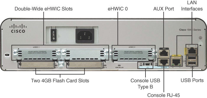
Figure 31-9 Backplane of the Cisco 1941 Router
Specialty Devices
Although switches and routers make up the backbone of a network, many networks integrate various specialized network devices.
Firewalls
A firewall is a networking device, either hardware or software based, that controls access to the organization’s network. This controlled access is designed to protect data and resources from an outside threat.
Organizations implement software firewalls through a network operating system (NOS) such as Linux/UNIX, Windows servers, and Mac OS X servers. The firewall is configured on the server to allow or block certain types of network traffic. Hardware firewalls are often dedicated network devices that can be implemented with little configuration.
Figure 31-10 shows a basic stateful firewall.
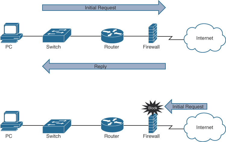
Figure 31-10 The Function of a Firewall
A stateful firewall allows traffic to originate from an inside, trusted network and go out to an untrusted network, such as the Internet. The firewall allows return traffic that comes back from the untrusted network to the trusted network. However, the firewall blocks traffic that originates from an untrusted network.
IDS and IPS
Both Intrusion Detection Systems (IDS) and Intrusion Prevention Systems (IPS) can recognize network attacks; they differ primarily in their network placement. An IDS device receives a copy of traffic to be analyzed. An IPS device is placed inline with the traffic, as Figure 31-11 shows.
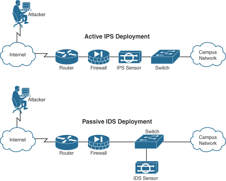
Figure 31-11 IPS and IDS Comparison
An IDS is a passive detection system. It can detect the presence of an attack, log the information, and send an alert.
An IPS has the same functionality as an IDS, but additionally, an IPS is an active device that continually scans the network, looking for inappropriate activity. It can shut down any potential threats. The IPS looks for any known signatures of common attacks and automatically tries to prevent those attacks.
Access Points and Wireless LAN Controllers
Wireless LANs (WLAN) are commonly a part of most networks. Users expect to be able to connect seamlessly as they move from location to location within a home, small business, or enterprise campus network. To enable this connectivity, network administrators manage a collection of wireless access points (AP) and wireless LAN controllers (WLC).
In small networks, APs are typically used when a router is already providing Layer 3 services, as in Figure 31-12.
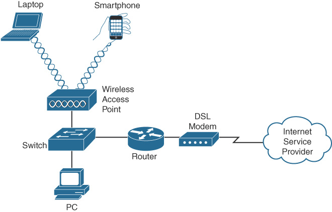
Figure 31-12 Small Network with an AP
An AP has an Ethernet port that enables it to be connected to a switch port. In a home or small office network, an AP can simply be another wireless router with all the Layer 3 services turned off. You simply connect one of the AP’s switch ports to the one of the switch ports on the wireless router.
APs are also used when the coverage area of an existing WLAN needs to be extended. In larger networks, a wireless LAN controller (WLC) is typically used to manage multiple APs, as in Figure 31-13.
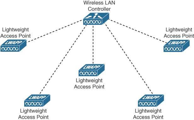
Figure 31-13 Example of a Wireless LAN Controller Implementation
WLCs can use the older Lightweight Access Point Protocol (LWAPP) or the more current Control and Provisioning of Wireless Access Points (CAPWAP). Using a WLC, VLAN pooling can be used to assign IP addresses to wireless clients from a pool of IP subnets and their associated VLANs.
Physical Layer
Before any network communications can occur, a wired or wireless physical connection must be established. The type of physical connection depends on the network setup. In larger networks, switches and APs are often two separate dedicated devices. In a very small business (three or four employees) or home network, wireless and wired connections are combined into one device and include a broadband method of connecting to the Internet. These wireless broadband routers offer a switching component with multiple ports and an AP, which allows wireless devices to connect as well. Figure 31-14 shows the back plane of a Cisco WRP500 Wireless Broadband Router.
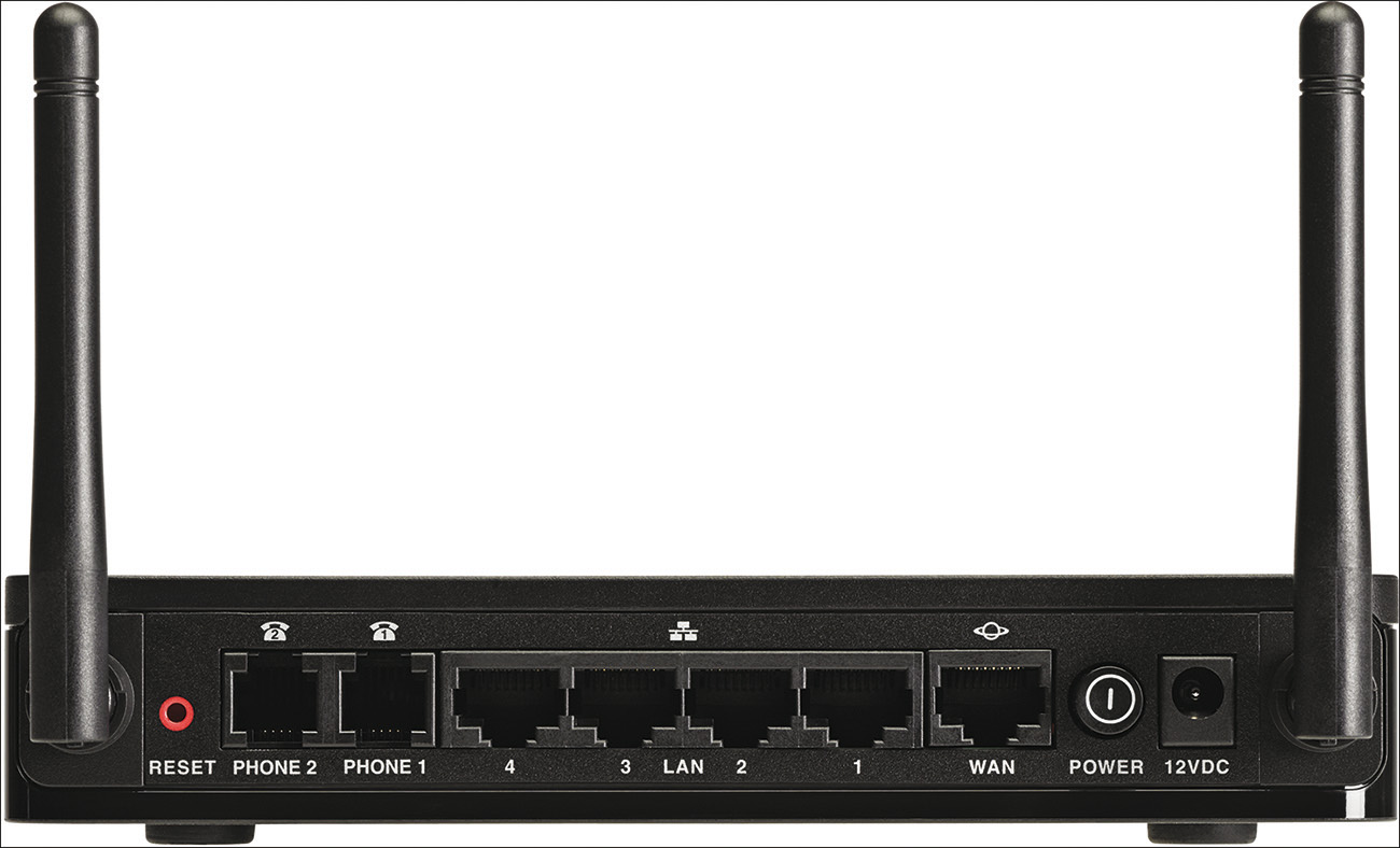
Figure 31-14 Cisco WRP500 Wireless Broadband Router
Network Media Forms and Standards
Three basic forms of network media exist:
- Copper cable: The signals are patterns of electrical pulses.
- Fiber-optic cable: The signals are patterns of light.
- Wireless: The signals are patterns of microwave transmissions.
Messages are encoded and then placed onto the media. Encoding is the process of converting data into patterns of electrical, light, or electromagnetic energy so that it can be carried on the media.
Table 31-6 summarizes the three most common networking media in use today.
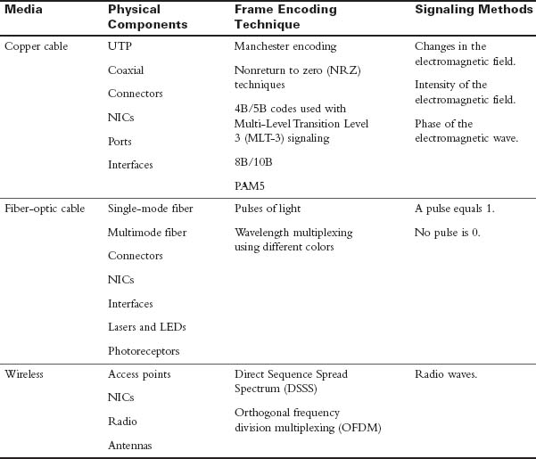
Table 31-6 Networking Media
Each media type has its advantages and disadvantages. When choosing the media, consider each of the following:
- Cable length: Does the cable need to span a room or run from building to building?
- Cost: Does the budget allow for using a more expensive media type?
- Bandwidth: Does the technology used with the media provide adequate bandwidth?
- Ease of installation: Does the implementation team have the capability to install the cable, or is a vendor required?
- Susceptible to EMI/RFI: Will the local environment interfere with the signal?
Table 31-7 summarizes the media standards for LAN cabling.
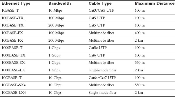
Table 31-7 Media Standard, Cable Length, and Bandwidth
LAN Device Connection Guidelines
End devices are pieces of equipment that are either the original source or the final destination of a message. Intermediary devices connect end devices to the network, to assist in getting a message from the source end device to the destination end device.
Connecting devices in a LAN is usually done with unshielded twisted-pair (UTP) cabling. Although many newer devices have an automatic crossover feature that enables you to connect either a straight-through or a crossover cable, you still need to know the following basic rules:
Use straight-through cables for the following connections:
- Switch to router Ethernet port
- Computer to switch
- Computer to hub
Use crossover cables for the following connections:
- Switch to switch
- Switch to hub
- Hub to hub
- Router to router (Ethernet ports)
- Computer to computer
- Computer to router Ethernet port
LANs and WANs
A local-area network (LAN) is a network of computers and other components located relatively close together in a limited area. LANs can vary widely in size, from one computer connected to a router in a home office, to hundreds of computers in a corporate office. However, in general, a LAN spans a limited geographical area. The fundamental components of a LAN include the following:
- Computers
- Interconnections (NICs and the media)
- Networking devices (hubs, switches, and routers)
- Protocols (Ethernet, IP, ARP, DHCP, DNS, and so on)
A wide-area network (WAN) generally connects LANs that are geographically separated. A collection of LANs connected by one or more WANs is called an internetwork—thus, we have the Internet. The term intranet is often used to refer to a privately owned connection of LANs and WANs.
Depending on the type of service, connecting to the WAN normally works in one of four ways:
- RJ-11 connection to a dialup or DSL modem
- Cable coaxial connection to a cable modem
- 60-pin serial connection to a CSU/DSU
- RJ-45 T1 controller connection to a CSU/DSU
With the growing number of teleworkers, enterprises have an increasing need for secure, reliable, and cost-effective ways to connect people working in small offices or home offices (SOHO) or other remote locations to resources on corporate sites. Remote connection technologies to support teleworkers include the following:
- Traditional private WAN technologies, including Frame Relay, ATM, and leased lines
- IPsec virtual private networks (VPN)
- Remote secure VPN access through a broadband connection over the public Internet
Components needed for teleworker connectivity include the following:
- Home office components: Computer, broadband access (cable or DSL), and a VPN router or VPN client software installed on the computer
- Corporate components: VPN-capable routers, VPN concentrators, multifunction security appliances, authentication, and central management devices for resilient aggregation and termination of the VPN connections
Networking Icons
Before you can interpret networking diagrams or topologies, you must understand the symbols or icons used to represent different networking devices and media. The icons in Figure 31-7 are the most common networking symbols for CCNA studies.
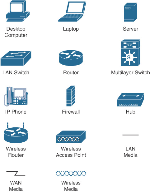
Figure 31-15 Networking Icons
Physical and Logical Topologies
Network diagrams are usually referred to as topologies. A topology graphically displays the interconnection methods used between devices.
Physical topologies refer to the physical layout of devices and how they are cabled. Seven basic physical topologies exist (see Figure 31-16).
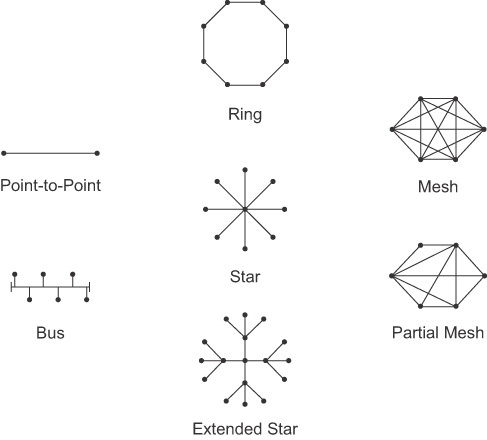
Figure 31-16 Physical Topologies
Logical topologies refer to the way that a signal travels from one point on the network to another and are largely determined by the access method—deterministic or nondeterministic. Ethernet is a nondeterministic access method. Logically, Ethernet operates as a bus topology. However, Ethernet networks are almost always physically designed as a star or extended star.
Other access methods use a deterministic access method. Token Ring and Fiber Distributed Data Interface (FDDI) both logically operate as a ring, passing data from one station to the next. Although these networks can be designed as a physical ring, like Ethernet, they are often designed as a star or extended star. Logically, however they operate like a ring.
Activity: Determine the Device Type
Hierarchical Campus Designs
Hierarchical campus design involves dividing the network into discrete layers. Each layer provides specific functions that define its role within the overall network. By separating the various functions that exist on a network, the network design becomes modular, which facilitates scalability and performance. The hierarchical design model is divided into three layers:
- Access layer: Provides local and remote user access
- Distribution layer: Controls the flow of data between the access and core layers
- Core layer: Acts as the high-speed redundant backbone
Figure 31-17 shows an example of the three-tiered hierarchical campus network design.
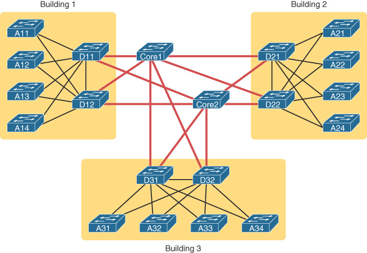
Figure 31-17 Three-Tiered Campus Design
For smaller networks, the core is often collapsed into the distribution layer for a two-tiered design, as in Figure 31-18.
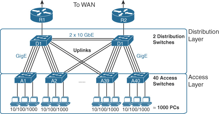
Figure 31-18 Three-Tiered Campus Design
A two-tier design solves two major design needs:
- Provides a place to connect end-user devices (the access layer, with access switches)
- Connects the switches with a reasonable number of cables and switch ports by connecting all 40 access switches to two distribution switches
For very small networks and home networks, all three tiers can be seen in one device, such as the wireless broadband router shown earlier in Figure 31-14.
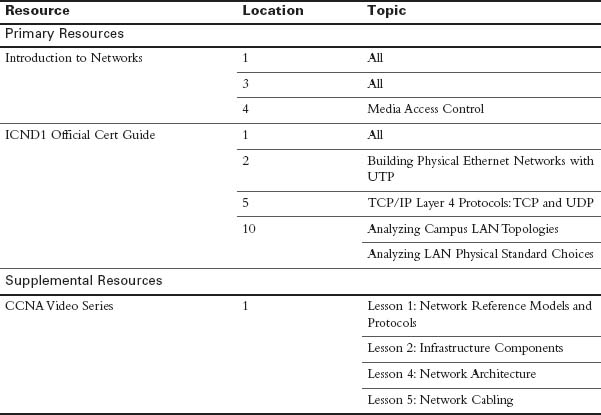
Study Resources
For today’s exam topics, refer to the following resources for more study.
 Check Your Understanding