Day 30. Ethernet Switching
CCNA 200-125 Exam Topics
- Describe and verify switching concepts
- Interpret Ethernet frame format
Key Topics
Today we review the concepts behind Ethernet switching, including the history of switching development, how switching actually works, and the variety of switch features. We also review how to access Cisco devices, the basic IOS commands to navigate the command-line interface (CLI), and the details of Ethernet operation.
Evolution to Switching
Today’s LANs almost exclusively use switches to interconnect end devices; however, this was not always the case. Initially, devices were connected to a physical bus, a long run of coaxial backbone cabling. With the introduction of 10BASE-T and UTP cabling, the hub gained popularity as a cheaper, easier way to connect devices. But even 10BASE-T with hubs had the following limitations:
- A frame sent from one device can collide with a frame sent by another device attached to that LAN segment. Devices were in the same collision domain sharing the bandwidth.
- Broadcasts sent by one device were heard and processed by all other devices on the LAN. Devices were in the same broadcast domain. Similar to hubs, switches forward broadcast frames out all ports except for the incoming port.
Ethernet bridges were soon developed to solve some of the inherent problems in a shared LAN. A bridge basically segmented a LAN into two collision domains, which reduced the number of collisions in a LAN segment. This increased the performance of the network by decreasing unnecessary traffic from another segment.
When switches arrived on the scene, these devices provided the same benefits of bridges, in addition to the following:
- A larger number of interfaces to break up the collision domain into more segments
- Hardware-based switching instead of using software to make the decision
In a LAN where all nodes are connected directly to the switch, the throughput of the network increases dramatically. With each computer connected to a separate port on the switch, each is in a separate collision domain and has its own dedicated segment. The three primary reasons for this increase follow:
- Dedicated bandwidth to each port
- Collision-free environment
- Full-duplex operation
Switching Logic
Ethernet switches selectively forward individual frames from a receiving port to the port where the destination node is connected. During this instant, the switch creates a full-bandwidth, logical, point-to-point connection between the two nodes.
Switches create this logical connection based on the source and destination Media Access Control (MAC) addresses in the Ethernet header. Specifically, the primary job of a LAN switch is to receive Ethernet frames and then make a decision to either forward the frame or ignore the frame. To accomplish this, the switch performs three actions:
1. Decides when to forward a frame or when to filter (not forward) a frame, based on the destination MAC address
2. Learns MAC addresses by examining the source MAC address of each frame the switch receives
3. Creates a (Layer 2) loop-free environment with other switches by using Spanning Tree Protocol (STP)
To make the decision to forward or filter, the switch uses a dynamically built MAC address table stored in RAM. By comparing the frame’s destination MAC address with the fields in the table, the switch decides how to forward and/or filter the frame.
For example, in Figure 30-1, the switch receives a frame from Host A with the destination MAC address OC. The switch looks in its MAC table, finds an entry for the MAC address, and forwards the frame out port 6. The switch also filters the frame by not forwarding it out any other port, including the port on which the frame was received.
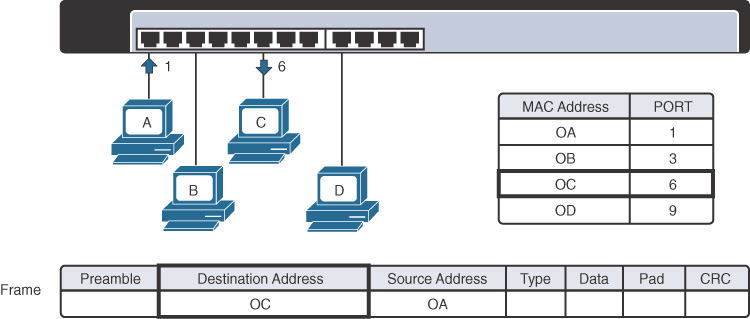
Figure 30-1 Switch Forwarding Based on MAC Address
In addition to forwarding and filtering frames, the switch refreshes the timestamp for the source MAC address of the frame. In Figure 30-1, the MAC address for Host A, OA, is already in the MAC table, so the switch refreshes the entry. Entries that are not refreshed eventually are removed (after the default 300 seconds in Cisco IOS).
Continuing the example in Figure 30-1, assume that another device, Host E, is attached to port 10. Host B then sends a frame to the new Host E. The switch does not yet know where Host E is located, so it forwards the frame out all active ports except for the port on which the frame was received. The new Host E receives the frame. When it replies to Host B, the switch learns Host E’s MAC address and port for the first time and stores it in the MAC address table. Subsequent frames destined for Host E then are sent out only port 10.
Finally, LAN switches must have a method for creating a loop-free path for frames to take within the LAN. Spanning Tree Protocol (STP) provides loop prevention in Ethernet networks where redundant physical links exist.
Collision and Broadcast Domains
A collision domain is the set of LAN interfaces whose frames could collide with each other. All shared media environments, such as those created by using hubs, are collision domains. When one host is attached to a switch port, the switch creates a dedicated connection, thereby eliminating the potential for a collision. Switches reduce collisions and improve bandwidth use on network segments because they provide dedicated bandwidth to each network segment.
Out of the box, however, a switch cannot provide relief from broadcast traffic. A collection of connected switches forms one large broadcast domain. If a frame with the destination address FFFF.FFFF.FFFF crosses a switch port, that switch must flood the frame out all other active ports. Each attached device must then process the broadcast frame at least up to the network layer. Routers and VLANs are used to segment broadcast domains. Day 28, “VLAN and Trunking Concepts and Configuration,” reviews the use of VLANs to segment broadcast domains.
Frame Forwarding
Switches operate in several ways to forward frames. They can differ in forwarding methods, port speeds, memory buffering, and the OSI layers used to make the forwarding decision. The following sections discuss these concepts in greater detail.
Switch Forwarding Methods
Switches use one of the following forwarding methods to switch data between network ports:
- Store-and-forward switching: The switch stores received frames in its buffers, analyzes each frame for information about the destination, and evaluates the data integrity using the cyclic redundancy check (CRC) in the frame trailer. The entire frame is stored and the CRC is calculated before any of the frame is forwarded. If the CRC passes, the frame is forwarded to the destination.
- Cut-through switching: The switch buffers just enough of the frame to read the destination MAC address so that it can determine which port to forward the data. When the switch determines a match between the destination MAC address and an entry in the MAC address table, the frame is forwarded out the appropriate port(s). This happens as the rest of the initial frame is still being received. The switch does not perform any error checking on the frame.
- Fragment free: The switch waits for the collision window (64 bytes) to pass before forwarding the frame. This means that each frame is checked into the data field to make sure that no fragmentation has occurred. Fragment-free mode provides better error checking than cut-through, with practically no increase in latency.
 Activity: Identify the Frame Forwarding Method
Symmetric and Asymmetric Switching
Symmetric switching provides switched connections between ports with the same bandwidth, such as all 100 Mbps ports or all 1000 Mbps ports. An asymmetric LAN switch provides switched connections between ports of unlike bandwidth, such as a combination of 10 Mbps, 100 Mbps, and 1000 Mbps ports.
Memory Buffering
Switches store frames for a brief time in a memory buffer. Two methods of memory buffering exist:
- Port-based memory: Frames are stored in queues that are linked to specific incoming ports.
- Shared memory: Frames are deposited into a common memory buffer that all ports on the switch share.
Layer 2 and Layer 3 Switching
A Layer 2 LAN switch performs switching and filtering based only on MAC addresses. A Layer 2 switch is completely transparent to network protocols and user applications. A Layer 3 switch functions similarly to a Layer 2 switch. But instead of using only the Layer 2 MAC address information for forwarding decisions, a Layer 3 switch can also use IP address information. Layer 3 switches are also capable of performing Layer 3 routing functions, reducing the need for dedicated routers on a LAN. Because Layer 3 switches have specialized switching hardware, they can typically route data as quickly as they can switch data.
Ethernet Overview
802.3 is the IEEE standard for Ethernet, and both terms are commonly used interchangeably. The terms Ethernet and 802.3 both refer to a family of standards that together define the physical and data link layers of the definitive LAN technology. Figure 30-2 shows a comparison of Ethernet standards to the OSI model.
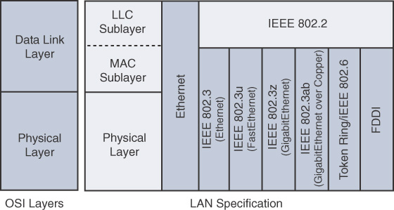
Figure 30-2 Ethernet Standards and the OSI Model
Ethernet separates the functions of the data link layer into two distinct sublayers:
- Logical Link Control (LLC) sublayer: Defined in the 802.2 standard
- Media Access Control (MAC) sublayer: Defined in the 802.3 standard
The LLC sublayer handles communication between the network layer and the MAC sublayer. In general, LLC provides a way to identify the protocol that is passed from the data link layer to the network layer. In this way, the fields of the MAC sublayer are not populated with protocol type information, as was the case in earlier Ethernet implementations.
The MAC sublayer has two primary responsibilities:
- Data encapsulation: Included here is frame assembly before transmission, frame parsing upon reception of a frame, data link layer MAC addressing, and error detection.
- Media Access Control: Because Ethernet is a shared media and all devices can transmit at any time, media access is controlled by a method called Carrier Sense Multiple Access with Collision Detection (CSMA/CD) when operating in half-duplex mode.
At the physical layer, Ethernet specifies and implements encoding and decoding schemes that enable frame bits to be carried as signals across both unshielded twisted-pair (UTP) copper cables and optical fiber cables. In early implementations, Ethernet used coaxial cabling.
Legacy Ethernet Technologies
Ethernet is best understood by first considering the two early Ethernet specifications, 10BASE5 and 10BASE2. With these two specifications, the network engineer installs a series of coaxial cables connecting each device on the Ethernet network, as in Figure 30-3.
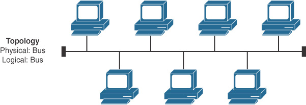
Figure 30-3 Ethernet Physical and Logical Bus Topology
The series of cables creates an electrical circuit, called a bus, that is shared among all devices on the Ethernet. When a computer wants to send some bits to another computer on the bus, it sends an electrical signal and the electricity propagates to all devices on the Ethernet.
With the change of media to UTP and the introduction of the first hubs, Ethernet physical topologies migrated to a star, as shown in Figure 30-4.
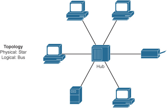
Figure 30-4 Ethernet Physical Star and Logical Bus Topology
Regardless of the change in the physical topology from a bus to a star, hubs logically operate similarly to a traditional bus topology and require the use of CSMA/CD.
CSMA/CD
Because Ethernet is a shared media in which every device has the right to send at any time, it also defines a specification to ensure that only one device sends traffic at a time. The CSMA/CD algorithm defines how the Ethernet logical bus is accessed.
CSMA/CD logic helps prevent collisions and also defines how to act when a collision does occur. The CSMA/CD algorithm works like this:
1. A device with a frame to send listens until the Ethernet is not busy.
2. When the Ethernet is not busy, the sender(s) begin(s) sending the frame.
3. The sender(s) listen(s) to make sure that no collision occurs.
4. If a collision occurs, the devices that were sending a frame each send a jamming signal to ensure that all stations recognize the collision.
5. When the jamming is complete, each sender randomizes a timer and waits that long before trying to resend the collided frame.
6. When each random timer expires, the process starts again from the beginning.
When CSMA/CD is in effect, a device’s network interface card (NIC) operates in half-duplex mode, either sending or receiving frames. CSMA/CD is disabled when a NIC autodetects that it can operate in—or is manually configured to operate in—full-duplex mode. In full-duplex mode, a NIC can send and receive simultaneously.
Legacy Ethernet Summary
LAN hubs occasionally appear, but switches generally are used instead of hubs. Keep in mind the following key points about the history of Ethernet:
- The original Ethernet LANs created an electrical bus to which all devices connected.
- 10BASE2 and 10BASE5 repeaters extended the length of LANs by cleaning up the electrical signal and repeating it (a Layer 1 function), but without interpreting the meaning of the electrical signal.
- Hubs are repeaters that provide a centralized connection point for UTP cabling—but they still create a single electrical bus that the various devices share, just as with 10BASE5 and 10BASE2.
- Because collisions can occur in any of these cases, Ethernet defines the CSMA/CD algorithm, which tells devices how to both avoid collisions and take action when collisions do occur.
Current Ethernet Technologies
Refer to Figure 30-1 and notice the different 802.3 standards. Each new physical layer standard from the IEEE requires many differences at the physical layer. However, each of these physical layer standards uses the same 802.3 header, and each uses the upper LLC sublayer as well. Table 30-1 lists today’s most commonly used IEEE Ethernet physical layer standards.
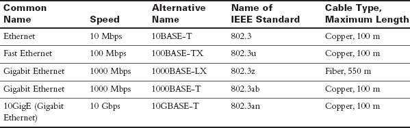
Table 30-1 Today's Most Common Types of Ethernet
UTP Cabling
The three most common Ethernet standards used today—10BASE-T (Ethernet), 100BASE-TX (Fast Ethernet, or FE), and 1000BASE-T (Gigabit Ethernet, or GE)—use UTP cabling. Some key differences exist, particularly with the number of wire pairs needed in each case and in the type (category) of cabling.
The UTP cabling in popular Ethernet standards includes either two or four pairs of wires. The cable ends typically use an RJ-45 connector. The RJ-45 connector has eight specific physical locations into which the eight wires in the cable can be inserted; these are called pin positions or, simply, pins.
The Telecommunications Industry Association (TIA) and the Electronics Industry Alliance (EIA) define standards for UTP cabling, with color coding for wires and standard pinouts on the cables. Figure 30-5 shows two TIA/EIA pinout standards, with the color coding and pair numbers listed.
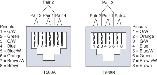
Figure 30-5 TIA/EIA Standard Ethernet Cabling Pinouts
For the exam, you should be well prepared to choose which type of cable (straight-through or crossover) is needed in each part of the network. In short, devices on opposite ends of a cable that use the same pair of pins to transmit need a crossover cable. Devices that use an opposite pair of pins to transmit need a straight-through cable. Table 30-2 lists typical devices and the pin pairs they use, assuming that they use 10BASE-T and 100BASE-TX.
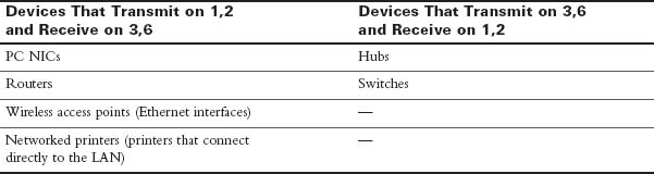
Table 30-2 10BASE-T and 100BASE-TX Pin Pairs Used
1000BASE-T requires four wire pairs because Gigabit Ethernet transmits and receives on each of the four wire pairs simultaneously.
However, Gigabit Ethernet does have a concept of straight-through and crossover cables, with a minor difference in the crossover cables. The pinouts for a straight-through cable are the same—pin 1 to pin 1, pin 2 to pin 2, and so on.
A crossover cable has the 568A standard on one end and the 568B standard on the other end. This crosses the pairs at pins 1,2 and 3,6.
Activity: Identify the 568A Pinouts
Activity: Identify the 568B Pinouts
Benefits of Using Switches
A collision domain is a set of devices whose frames may collide. All devices on a 10BASE2, 10BASE5, or other network using a hub risk collisions between the frames that they send. Thus, so devices on one of these types of Ethernet networks are in the same collision domain and use CSMA/CD to detect and resolve collisions.
LAN switches significantly reduce, or even eliminate, the number of collisions on a LAN. Unlike hubs, switches do not create a single shared bus. Instead, switches do the following:
- They interpret the bits in the received frame so that they can typically send the frame out the one required port instead of out all other ports.
- If a switch needs to forward multiple frames out the same port, the switch buffers the frames in memory, sending one at a time and thereby avoiding collisions.
In addition, switches with only one device cabled to each port of the switch allow the use of full-duplex operation. Full-duplex operation means that the NIC can send and receive concurrently, effectively doubling the bandwidth of a 100 Mbps link to 200 Mbps—100 Mbps for sending and 100 Mbps for receiving.
These seemingly simple switch features provide significant performance improvements, compared with using hubs. In particular, consider these points:
- If only one device is cabled to each port of a switch, no collisions can occur.
- Devices connected to one switch port do not share their bandwidth with devices connected to another switch port. Each has its own separate bandwidth, meaning that a switch with 100 Mbps ports has 100 Mbps of bandwidth per port.
Ethernet Addressing
The IEEE defines the format and assignment of LAN addresses. To ensure a unique MAC address, the first half of the address identifies the manufacturer of the card. This code is called the organizationally unique identifier (OUI). Each manufacturer assigns a MAC address with its own OUI as the first half of the address. The second half of the address is assigned by the manufacturer and is never used on another card or network interface with the same OUI. Figure 30-6 shows the structure of a unicast Ethernet address.
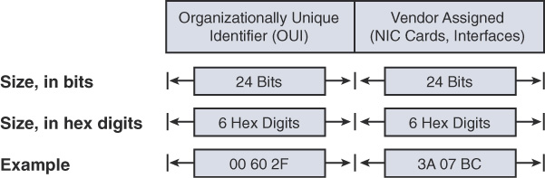
Figure 30-6 Structure of a Unicast Ethernet Address
Ethernet also has group addresses, which identify more than one NIC or network interface. The IEEE defines two general categories of group addresses for Ethernet:
- Broadcast addresses: The broadcast address implies that all devices on the LAN should process the frame and has a value of FFFF.FFFF.FFFF.
- Multicast addresses: Multicast addresses allow a subset of devices on a LAN to communicate. When IP multicasts over an Ethernet, the multicast MAC addresses that IP uses follow this format: 0100.5exx.xxxx. The xx.xxxx portion is divided between IPv4 multicast (00:0000–7F.FFFF) and MPLS multicast (80:0000–8F:FFFF). Multiprotocol Label Switching (MPLS) is a CCNP topic.
Ethernet Framing
The physical layer helps you get a string of bits from one device to another. The framing of the bits allows the receiving device to interpret the bits. The term framing refers to the definition of the fields assumed to be in the data that is received. Framing defines the meaning of the bits transmitted and received over a network.
The framing used for Ethernet has changed a couple times over the years. Figure 30-7 shows each iteration of Ethernet, with the current version shown at the bottom.
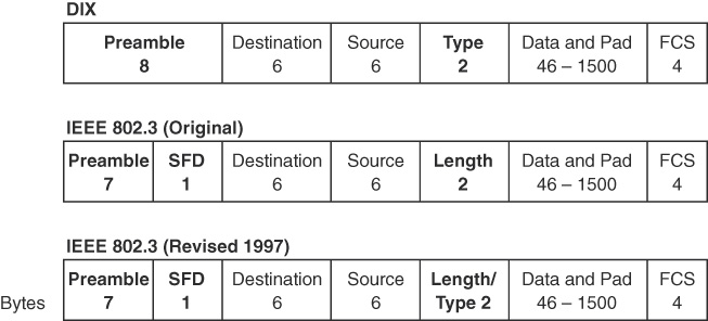
Figure 30-7 Ethernet Frame Formats
Table 30-3 further explains the fields in the last version shown in Figure 30-6.
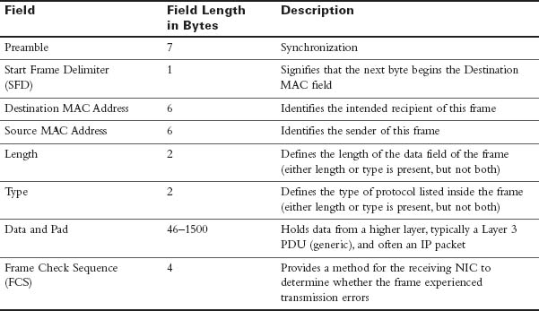
Table 30-3 IEEE 802.3 Ethernet Field Descriptions
Activity: Order the Fields in a Frame
The Role of the Physical Layer
We have already discussed the most popular cabling used in LANs: UTP. To fully understand the operation of the network, you should know some additional basic concepts of the physical layer.
The OSI physical layer accepts a complete frame from the data link layer and encodes it as a series of signals that are transmitted onto the local media.
The delivery of frames across the local media requires the following physical layer elements:
- The physical media and associated connectors
- A representation of bits on the media
- Encoding of data and control information
- Transmitter and receiver circuitry on the network devices
Data is represented on three basic forms of network media:
- Copper cable
- Fiber
- Wireless (IEEE 802.11)
Bits are represented on the medium by changing one or more of the following characteristics of a signal:
- Amplitude
- Frequency
- Phase
The nature of the actual signals representing the bits on the media depends on the signaling method in use. Some methods use one attribute of a signal to represent a single 0 and use another attribute of a signal to represent a single 1. The actual signaling method and its detailed operation are not important to your CCNA exam preparation.
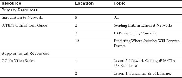
Study Resources
For today’s exam topics, refer to the following resources for more study.
 Check Your Understanding