Day 31. Network Devices, Components, and Applications
CCENT 100-101 ICND1 Exam Topics
- Recognize the purpose and functions of various network devices such as routers, switches, bridges, and hubs.
- Select the components required to meet a given network specification.
- Identify the appropriate media, cables, ports, and connectors to connect Cisco network devices to other network devices and hosts in a LAN.
- Identify common applications and their impact on the network.
Key Points
At its most fundamental level, a network can be divided into four elements:
- The devices
- The media
- The rules
- The messages
For today’s exam topics, we will focus on the devices used in today’s networks, the media used to interconnect those devices, and the different types of network topologies.
Devices
In today’s networks, switches are almost exclusively used to connect end devices to a single LAN. On occasion, you might see a hub connecting end devices. But hubs are really legacy devices. The following describes the difference between a hub and a switch:
- Hubs were typically chosen as an intermediary device within a very small LAN, where bandwidth usage was not an issue or there were cost limitations. In today’s networks, hubs have been replaced by switches.
- Switches replaced hubs as the local area network (LAN) intermediary device because a switch can segment collision domains and provide enhanced security.
Switches
When choosing a switch, the main factors to consider are the following:
- Cost: Determined by the number and type of ports, network management capabilities, embedded security technologies, and optional advanced switching technologies.
- Interface characteristics: Sufficient number of ports for now as well as for future expansion, uplink speeds, mixture of UTP and fiber, and modularity.
- Hierarchical network layer: Switches at the access layer have different requirements than switches at the distribution or core layers.
Access Layer Switches
Access layer switches facilitate the connection of end devices to the network. Features of access layer switches include the following:
- Port security
- VLANs
- Fast Ethernet/Gigabit Ethernet
- Power over Ethernet (PoE)
- Link aggregation
- Quality of service (QoS)
Distribution Layer Switches
Distribution layer switches receive the data from the access layer switches and forward it to the core layer switches. Features of distribution layer switches include the following:
- Layer 3 support
- High forwarding rate
- Gigabit Ethernet/10 Gigabit Ethernet
- Redundant components
- Security policies/access control lists
- Link aggregation
- Quality of service (QoS)
Core Layer Switches
Core layer switches make up the backbone and are responsible for handling the majority of data on a switched LAN. Features of core layer switches include the following:
- Layer 3 support
- Very high forwarding rate
- Gigabit Ethernet/10 Gigabit Ethernet
- Redundant components
- Link aggregation
- Quality of service (QoS)
Routers
Routers are the primary devices used to interconnect networks—LANs, WANs, and WLANs. When choosing a router, the main factors to consider are the following:
- Expandability: Provides flexibility to add new modules as needs change.
- Media: Determines the type of interfaces the router needs to support the various network connections.
- Operating system features: Determines the version of IOS loaded on the router. Different IOS versions support different feature sets. Features to consider include security, QoS, Voice over IP (VoIP), routing complexity, and other services.
Figure 31-1 shows a Cisco 1941 router, which provides the following connections:
- Console ports: Two console ports for the initial configuration using a regular RJ-45 port and a new USB Type-B (mini-B USB) connector
- AUX port: An RJ-45 port for remote management access
- LAN interfaces: Two Gigabit Ethernet interfaces for LAN access
- Enhanced high-speed WAN interface card (eHWIC) slots: Two slots that support different types of interface modules, including serial, digital subscriber line (DSL), switch port, and wireless
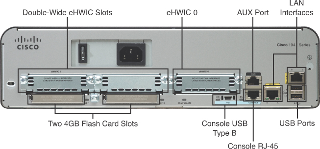
Figure 31-1 Backplane of the Cisco 1941 Router
Also shown in Figure 31-1 are two 4GB compact flash slots to provide increased storage space.
Video 31.1—The Purpose and Differences Between Switches and Routers
Physical Layer
Before any network communications can occur, a wired or wireless physical connection must be established. The type of physical connection depends on the network setup. In larger networks, switches and wireless access points (WAP) are often two separate dedicated devices. In a very small business (three or four employees) or home network, integrated service routers (ISR) are usually implemented. These ISRs offer a switching component with multiple ports and a WAP, which allows wireless devices to connect as well. Figure 31-2 shows the Linksys E2500, a typical small network ISR.
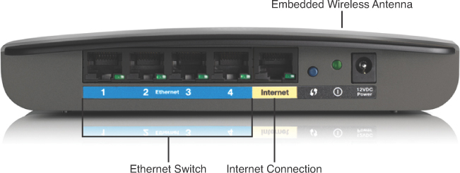
Figure 31-2 Example of an ISR: Linksys E2500
Network Media Forms and Standards
There are three basic forms of network media:
- Copper cable: The signals are patterns of electrical pulses.
- Fiber-optic cable: The signals are patterns of light.
- Wireless: The signals are patterns of microwave transmissions.
Messages are encoded and then placed on the media. Encoding is the process of converting data into patterns of electrical, light, or electromagnetic energy so that it can be carried on the media.
Table 31-1 summarizes the three most common networking media in use today.
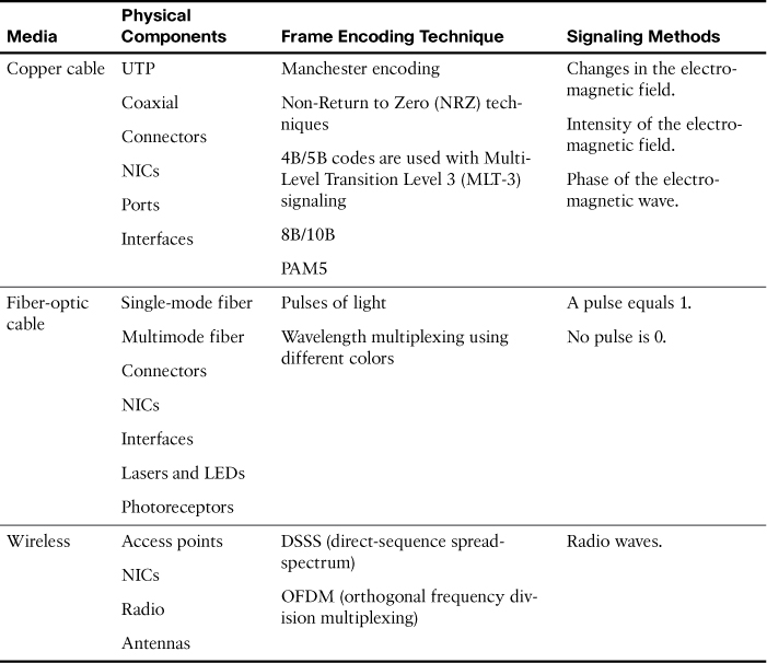
Table 31-1 Networking Media
Each media type has its advantages and disadvantages. When choosing the media, consider each of the following:
- Cable length: Does the cable need to span across a room or from building to building?
- Cost: Does the budget allow for using a more expensive media type?
- Bandwidth: Does the technology used with the media provide adequate bandwidth?
- Ease of installation: Does the implementation team have the ability to install the cable, or is a vendor required?
- Susceptible to EMI/RFI: Is the local environment going to interfere with the signal?
Table 31-2 summarizes media standards for LAN cabling.
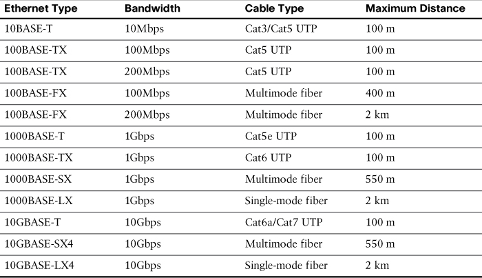
Table 31-2 Media Standard, Cable Length, and Bandwidth
LAN Device Connection Guidelines
End devices are those pieces of equipment that are either the original source or the final destination of a message. Intermediary devices connect end devices to the network to assist in getting a message from the source end device to the destination end device.
Connecting devices in a LAN is usually done with unshielded twisted-pair (UTP) cabling. Although many newer devices have an automatic crossover feature that allows you to connect either a straight-through or crossover cable, you should still know the following basic rules:
Use straight-through cables for the following connections:
- Switch to router Ethernet port
- Computer to switch
- Computer to hub
Use crossover cable for the following connections:
- Switch to switch
- Switch to hub
- Hub to hub
- Router to router (Ethernet ports)
- Computer to computer
- Computer to router Ethernet port
Video 31.2—The Three Basic Media Types: Copper, Fiber, Wireless
LANs and WANs
A local area network (LAN) is a network of computers and other components located relatively close together in a limited area. LANs can vary widely in size from one computer connected to a router in a home office to hundreds of computers in a corporate office; however, in general, a LAN spans a limited geographical area. The fundamental components of a LAN include the following:
- Computers
- Interconnections (NICs and the media)
- Networking devices (hubs, switches, and routers)
- Protocols (Ethernet, IP, ARP, DHCP, DNS, and so on)
A wide area network (WAN) generally connects LANs that are geographically separated. A collection of LANs connected by one or more WANs is called an internetwork—thus, we have the Internet. The term intranet is often used to refer to a privately owned connection of LANs and WANs.
Depending on the type of service, connecting to the WAN is normally done in one of four ways:
- RJ-11 connection to a dialup or DSL modem
- Cable coaxial connection to a cable modem
- 60-pin serial connection to a CSU/DSU
- RJ-45 T1 controller connection to a CSU/DSU
With the growing number of teleworkers, enterprises have an increasing need for secure, reliable, and cost-effective ways to connect people working in small offices or home offices (SOHO) or other remote locations to resources on corporate sites. Remote connection technologies to support teleworkers include the following:
- Traditional private WAN technologies, including Frame Relay, ATM, and leased lines
- IPsec virtual private networks (VPN)
- Remote secure VPN access through a broadband connection over the public Internet
Components needed for teleworker connectivity include the following:
- Home office components: Computer, broadband access (cable or DSL), and a VPN router or VPN client software installed on the computer
- Corporate components: VPN-capable routers, VPN concentrators, multifunction security appliances, authentication, and central management devices for resilient aggregation and termination of the VPN connections
Networking Icons
Before you can interpret networking diagrams or topologies, you first must understand the symbols or icons used to represent different networking devices and media. The icons shown in Figure 31-3 are the most common networking symbols for CCNA studies.
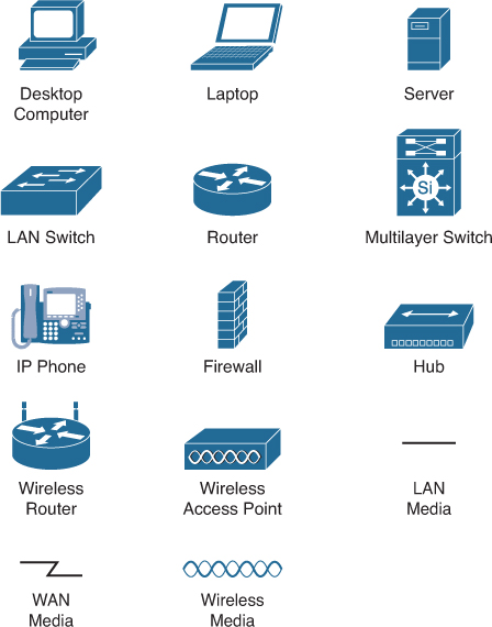
Figure 31-3 Networking Icons
Physical and Logical Topologies
Network diagrams are more often referred to as topologies. A topology graphically displays the interconnection methods used between devices.
Physical topologies refer to the physical layout of devices and how they are cabled. There are seven basic physical topologies, as shown in Figure 31-4.
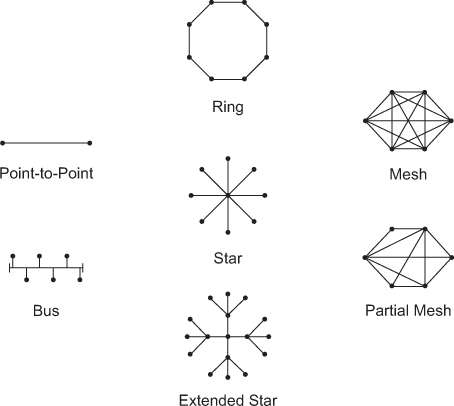
Figure 31-4 Physical Topologies
Logical topologies refer to the way that a signal travels from one point on the network to another and are largely determined by the access method—deterministic or nondeterministic. Ethernet is a nondeterministic access method. Logically, Ethernet operates as a bus topology. However, Ethernet networks are almost always physically designed as a star or extended star.
Other access methods use a deterministic access method. Token Ring and Fiber Distributed Data Interface (FDDI) both logically operate as ring, passing data from one station to the next. Although these networks can be designed as a physical ring, like Ethernet, they are often designed as a star or extended star. But logically, they operate like a ring.
Exercise: Determine the Device Type
Cisco Borderless Network
Figure 31-5 illustrates the Cisco Borderless Network architecture, which uses a tiered approach to virtually collapse the network into a single borderless network. The topology uses several devices that are beyond the scope of a CCNA candidate. However, you can see that a large collection of routers and switches play a major role in the design. Also notice the presence of multilayer switches at the core of the network.
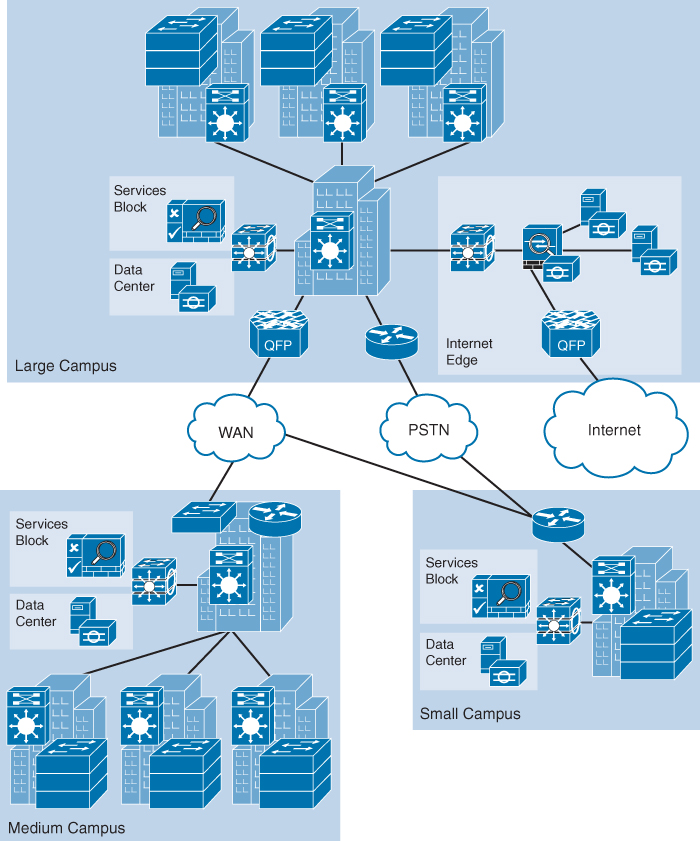
Figure 31-5 Cisco Borderless Network
The Cisco Borderless Network is a next-generation network architecture that allows organizations to connect anyone, anywhere, anytime, and on any device—securely, reliably, and seamlessly.
Hierarchy in a Borderless Network
Hierarchical network design involves dividing the network into discrete layers. Each layer provides specific functions that define its role within the overall network. By separating the various functions that exist on a network, the network design becomes modular, which facilitates scalability and performance. The hierarchical design model is broken up into three layers as follows:
- Access layer: Provides local and remote user access
- Distribution layer: Controls the flow of data between the access and core layers
- Core layer: High-speed redundant backbone
Figure 31-6 shows an example of the three-tiered hierarchical campus network design. For smaller networks, the core is often collapsed into the distribution layer for a two-tiered designed. And for very small networks and home networks, all three tiers can be seen in one device, such as the ISR shown earlier in Figure 31-2.
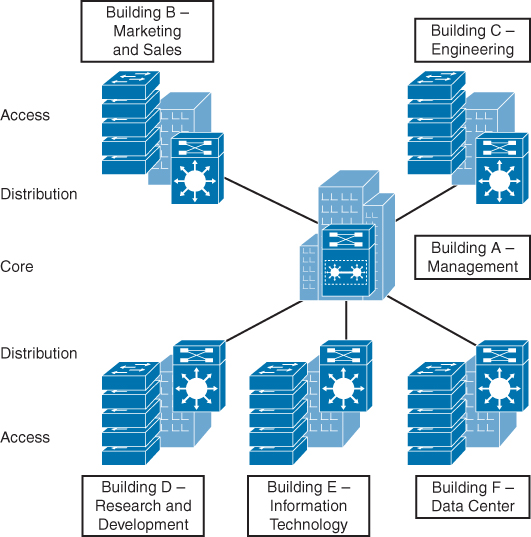
Figure 31-6 The Hierarchical Model
Network Documentation
Documentation for your network should include, at a minimum, the following major categories:
- Router and switch documentation: Includes device type, IOS image, host name, location, addresses, and other important information
- End-system documentation: Includes device names, OS, addressing details, and network impact (such as bandwidth usage)
- Network topology diagram: Includes all devices and shows the connections as well as the interface designations and addressing scheme
More often than not, a network’s documentation is less than complete. To complete the documentation, you might have to gather information directly from the devices. Commands that are useful to this process include the following:
- ping: Tests direct connectivity between two devices
- telnet: Tests remote access as well as Layer 7 functionality
- show ip interface brief: Verifies interface statuses
- show ip route: Verifies routing operations
- show cdp neighbor detail: Gathers useful information about directly connected Cisco devices
Classification of Network Applications
User applications can be classified into three broad categories of network impact:
- Batch applications, such as File Transfer Protocol (FTP) and other file transfer utilities that initially require a human to set up, but then run until completion without further human interaction. For these applications, bandwidth is important but not critical.
- Interactive applications, such as database queries where a human is requesting and inputting information into an application is more response-sensitive. Delays can be annoying, but bandwidth is still not critical.
- Real-time applications, such as Voice over IP (VoIP) and video, demand much more bandwidth. Installation of VoIP systems must be carefully provisioned so that the current network is not adversely affected.
User Application Interaction
There are basically two types of user interactions with a network application:
- Client-server: A client device requests information from a server. Requesting a web page from a server is an example of a client-server interaction.
- Peer-to-peer: A device acts as both a client and a server within the same communication. Each device in the network running the application can act as a client or a server for the other devices in the network. Text messaging is an example of a peer-to-peer interaction.
Common Network Applications
The following list briefly describes the most common network applications:
- Hypertext Transfer Protocol (HTTP) uses GET, POST, and PUT messages to transfer data between a web browser on a client device and a web server. For more secure communications, HTTPS uses authentication and encryption between the client and server.
- Simple Mail Transfer Protocol (SMTP) is used by an email client to send email messages to an email server.
- Post Office Protocol (POP) is used by an email client to download email messages from an email server.
- Domain Name System (DNS) is a distributed system of servers that resolves domain names to IP addresses. To access a web page, client devices must use the IP address. DNS discovers the IP address for a given Uniform Resource Locator (URL) or web address.
- Dynamic Host Configuration Protocol (DHCP) provides a method for a device to get IP addressing information from the network when it boots up or renews its IP address.
- File Transfer Protocol (FTP) is used by client devices to push and pull data to and from an FTP server.
- Server Message Block (SMB) is a file-sharing protocol that is common today in Microsoft networking. After a client device establishes a connection to server, the user can access resources on the server as if the resource is local to the client device.
Video 31.3—Common Network Applications
Growth of Network-Based Applications
Besides all the common applications we discuss in networking studies, programmers and entrepreneurs are continuously developing applications to take advantage of network resources and the Internet. Today, people create, store, and access information as well as communicate with others on the network using a variety of applications. In addition to the traditional email and web browser applications, people are increasingly using newer forms of communication, including instant messaging, blogs, podcasting, peer-to-peer file sharing, wikis, and collaborative tools that allow viewing and working on documents simultaneously. The online gaming industry has grown exponentially over the last decade. All of these applications and online experiences place great demands on the network infrastructure and resources. One way of handling the sheer volume of data is to rank packets based on the quality of service that the source application needs—especially considering the increased use of the network in general and the recent rise of voice and video applications that have a very low tolerance for delay and jitter.
Quality of Service
The priority and guaranteed level of service to the flow of data through the network are increasingly important as new applications place greater demands on the processing power and bandwidth of the networks we use. When we place a call over an IP phone, we want at least as good a service as we receive on a traditional land line. Therefore, networks need to use quality of service (QoS) mechanisms to ensure that limited network resources are prioritized based on traffic content. Without QoS implementation, an email message or web page request crossing a switch or a router will have the same priority as voice or video traffic.
Each type of application can be analyzed in terms of its QoS requirements on the network, so if the network meets those requirements, the application will work well.
Increased Network Usage
Applications have tended to increase the need for more bandwidth while, at the same time, demanding lower delay. Here are some of the types of data applications that have entered the marketplace and their impact on the network:
- Graphics-capable terminals and printers: Increase the required bytes for the same interaction as the old text-based terminals and printers
- File transfers: Introduce much larger volumes of data, but with no significant response time requirements
- File servers: Allow users to store files on a server—which might require a large volume of data transfer, but with a much smaller end-user response time requirement
- The maturation of database technology: Makes vast amounts of data available to casual users, vastly increasing the number of users wanting access to data
- The migration of common applications to web browsers: Encourages more users to access data
- The growth of email: The general acceptance of email as both a personal and business communications service has greatly increased the amount of email traffic.
- The rapid commercialization of the Internet: Enables companies to offer data directly to their customers through the data network rather than through phone calls
The Impact of Voice and Video on the Network
Currently, voice and video are in the midst of a migration to traditional IP data networks. Before the late 1990s, voice and video used separate networking facilities. Most companies today are either migrating or plan to migrate to IP phones, which pass voice data over the data network inside IP packets using application protocols generally referred to as Voice over IP (VoIP).
Figure 31-7 show a few details of how VoIP works from a home high-speed Internet connection, with a generic voice adapter (VA) converting the analog signal from a normal telephone to an IP packet.
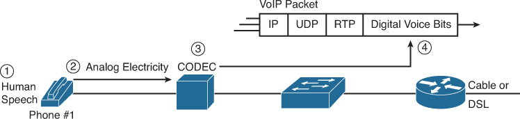
Figure 31-7 Converting from Sound to Packets with a VA
The demand that VoIP places on the data network is not for capacity. A voice call typically consumes less the 30kbps of bandwidth. However, VoIP is sensitive to delay, jitter, and packet loss:
- Low delay: VoIP requires a very low delay between the sending phone and the receiving phone—typically less than 200 milliseconds (0.2 seconds). This is a much lower delay than what is required by typical data applications.
- Low jitter: Jitter is the variation in delay. VoIP requires very low jitter as well, whereas data applications can tolerate much higher jitter. For example, the jitter for consecutive VoIP packets should not exceed 30 milliseconds (0.03 seconds), or the quality degrades.
- Loss: If a VoIP packet is lost in transit because of errors or because a router doesn’t have room to store the packet while waiting to send it, the lost VoIP packet is not retransmitted across the network. Lost packets can sound like a break in the sound of the VoIP call.
Video over IP has the same performance issues as voice. However, video requires a lot more bandwidth—anywhere from 300kbps to 10Mbps, depending on the quality demanded.
To support the QoS requirements of voice, video, and other quality- or time-sensitive applications, routers and switches can be configured with a wide variety of QoS tools. These configurations are beyond the scope of the CCNA exam topics.
Quiz