Day 30. Networking Models and Data Flow
CCENT 100-101 ICND1 Exam Topics
- Describe the purpose and basic operation of the protocols in the OSI and TCP/IP models.
- Predict the data flow between two hosts across a network.
Key Points
As a new student to networking, one of the very first topics you probably learned was the layers of the OSI and TCP/IP models. Now that you have completed your studies and are reviewing for your certification exam, you more than likely can see the benefit of using these models. Each helps our understanding of networks in its own way. Much of today’s review is a quick summary of the TCP/IP layers and their operations as data is sent from source to destination. Many of the key points will be fleshed out more fully in upcoming days. However, this is the only day we will discuss the operation of the transport layer. So we will spend quite a bit of time on the Transmission Control Protocol (TCP) and the User Datagram Protocol (UDP).
The OSI and TCP/IP Models
To understand how communication occurs across the network, we use layered models as a framework for representing and explaining networking concepts and technologies. Network models provide a variety of benefits:
- Reduce complexity
- Standardize interfaces
- Assist understanding
- Promote rapid product development
- Support interoperability
- Facilitate modular engineering
Initially, networks were built on proprietary standards and hardware. Layered models, such as the TCP/IP and OSI models, support interoperability between competing vendor product lines.
The OSI model development began in the 1970s with the goal of providing a standards-based suite of protocols that would allow communication among all computer systems. Although the U.S. government required the use of OSI products in the 1980s and 1990s, the Defense Advanced Research Projects Agency (DARPA) under the Department of Defense—and with the help of researchers at various universities—had designed the competing TCP/IP model. For various reasons, including the popularity of TCP/IP, by 1983, the ARPANET had chosen TCP/IP as its principal protocol suit. By 1994, all U.S. government agencies were required to switch over from OSI protocols to TCP/IP.
Today, we use the OSI model principally as a tool for explaining networking concepts. However, the protocols of the TCP/IP suite are the rules by which networks now operate. Because both models are important, you should be well versed in each model’s layers as well as how the models map to each other. Figure 30-1 summarizes the two models.
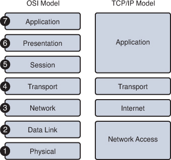
Figure 30-1 OSI and TCP/IP Models
It can be confusing using two models; however, these simple guidelines might help:
- When discussing layers of a model, we are usually referring to the OSI model.
- When discussing protocols, we are usually referring to the TCP/IP model.
So let’s quickly review the OSI layers and the TCP/IP protocols.
OSI Layers
Table 30-1 summarizes the layers of the OSI model and provides a brief functional description.
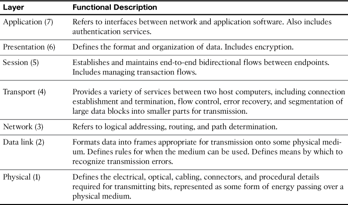
Table 30-1 OSI Model Layers and Functions
The following mnemonic phrase, where the first letter represents the layer (“A” stands for “Application”), can be helpful in memorizing the name and order of the layers from top to bottom:
All People Seem To Need Data Processing
TCP/IP Layers and Protocols
The TCP/IP model defines four categories of functions that must occur for communications to be successful. Most protocol models describe a vendor-specific protocol stack. However, because the TCP/IP model is an open standard, one company does not control the definition of the model.
Table 30-2 summarizes the TCP/IP layers, their functions, and the most common protocols.
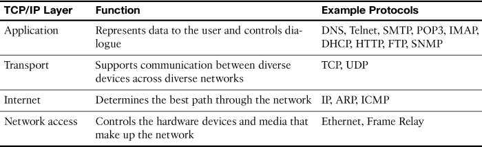
Table 30-2 TCP/IP Layer Functions
In the coming days, we will review these protocols in more detail. For now, a brief description of the main TCP/IP protocols follows:
- Domain Name System (DNS): Provides the IP address of a website or domain name so that a host can connect to it
- Telnet: Allows administrators to log in to a host from a remote location
- Simple Mail Transfer Protocol (SMTP), Post Office Protocol (POP3), and Internet Message Access Protocol (IMAP): Used to send email messages between clients and servers
- Dynamic Host Configuration Protocol (DHCP): Assigns IP addressing to requesting clients
- Hypertext Transfer Protocol (HTTP): Used to transfer information between web clients and web servers
- File Transfer Protocol (FTP): Allows the download and upload of files between an FTP client and FTP server
- Simple Network Management Protocol (SNMP): Used by network management systems to monitor devices attached to the network
- Transmission Control Protocol (TCP): Allows virtual connections between hosts on the network to provide reliable delivery of data
- User Datagram Protocol (UDP): Allows faster, unreliable delivery of data that is either lightweight or time-sensitive
- Internet Protocol (IP): Provides a unique global address to computers for communicating over the network
- Address Resolution Protocol (ARP): Finds a host’s hardware address when only the IP address is known
- Internet Control Message Protocol (ICMP): Used to send error and control messages, including reachability to another host and availability of services
- Ethernet: The most popular LAN standard for framing and preparing data for transmission onto the media
- Frame Relay: Also a framing standard; one of the most cost-effective WAN technologies used to connect LANs
Exercises: Order the Layers of the OSI and TCP-IP Models
Protocol Data Units and Encapsulation
As application data is passed down the protocol stack on its way to be transmitted across the network media, various protocols add information to it at each level. This is commonly known as the encapsulation process. The data structure at any given layer is called a protocol data unit (PDU). Table 30-3 lists the PDUs at each layer of the OSI model.
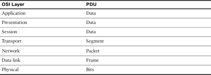
Table 30-3 PDUs at Each Layer of the OSI Model
The communication process from any source to any destination can be summarized with the following steps:
1. Creation of data at the application layer of the originating source device
2. Segmentation and encapsulation of data as it passes down the protocol stack in the source device
3. Generation of the data onto the media at the network access layer of the stack
4. Transportation of the data through the internetwork, which consists of media and any intermediary devices
5. Reception of the data at the network access layer of the destination device
6. Decapsulation and reassembly of the data as it passes up the stack in the destination device
7. Passing this data to the destination application at the application layer of the destination device
Video 30.1—The OSI and TCP/IP Models
The TCP/IP Application Layer
The application layer of the TCP/IP model provides an interface between software, like a web browser, and the network itself. The process of requesting and receiving a web page works like this:
1. HTTP request sent, including an instruction to “get” a file—which is often a website’s home page.
2. HTTP response sent from the web server with a code in the header—usually either 200 (request succeeded and information is returned in response) or 404 (page not found).
The HTTP request and the HTTP response are encapsulated in headers. The content of headers allows the application layers on each end device to communicate. Regardless of the application layer protocol (HTTP, FTP, DNS, and so on), all use the same general process for communicating between application layers on the end devices.
The TCP/IP Transport Layer
The transport layer, through TCP, provides a mechanism to guarantee delivery of data across the network. TCP supports error recovery to the application layer through the use of basic acknowledgment logic. Adding to the process for requesting a web page, TCP operation works like this:
1. Web client sends an HTTP request for a specific web server down to the transport layer.
2. TCP encapsulates the HTTP request with a TCP header and includes the destination port number for HTTP.
3. Lower layers process and send the request to the web server.
4. Web server receives HTTP requests and sends a TCP acknowledgment back to the requesting web client.
5. Web server sends the HTTP response down to the transport layer.
6. TCP encapsulates the HTTP data with a TCP header.
7. Lower layers process and send the response to the requesting web client.
8. Requesting web client sends acknowledgment back to the web server.
If data is lost at any point during this process, it is TCP’s job to recover the data. HTTP at the application layer does not get involved in error recovery.
In addition to TCP, the transport layer provides UDP—a connectionless, unreliable protocol for sending data that does not require nor need error recovery. Table 30-4 lists the main features supported by the transport protocols. The first item is supported by TCP and UDP. The remaining items are supported only by TCP.
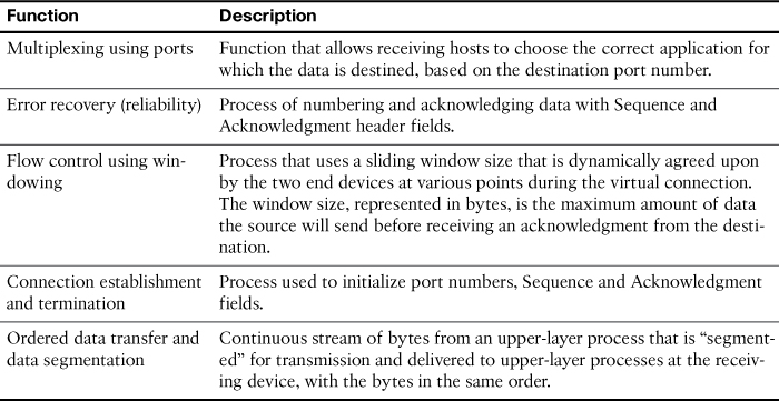
Table 30-4 TCP/IP Transport Layer Features
TCP Header
TCP provides error recovery, but to do so, it consumes more bandwidth and uses more processing cycles than UDP. TCP and UDP rely on IP for end-to-end delivery. TCP is concerned with providing services to the applications of the sending and receiving computers. To provide all these services, TCP uses a variety of fields in its header. Figure 30-2 shows the fields of the TCP header.
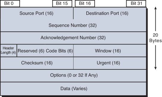
Figure 30-2 TCP Header
Port Numbers
The first two fields of the TCP header—source and destination ports—are also part of the UDP header shown later in Figure 30-6. Port numbers provide TCP (and UDP) with a way to multiplex multiple applications on the same computer. Web browsers now support multiple tabs or pages. Each time you open a new tab and request another web page, TCP assigns a different source port number and sometimes multiple port numbers. For example, you might have five web pages open. TCP will almost always assign destination port 80 for all five sessions. However, the source port for each will be different. This is how TCP (and UDP) multiplexes the conversation so that the web browser knows in which tab to display the data.
Source ports are usually dynamically assigned by TCP and UDP from the range starting 1024 up to a maximum of 65535. Port numbers below 1024 are reserved for well-known applications. Table 30-5 lists several popular applications and their well-known port numbers.
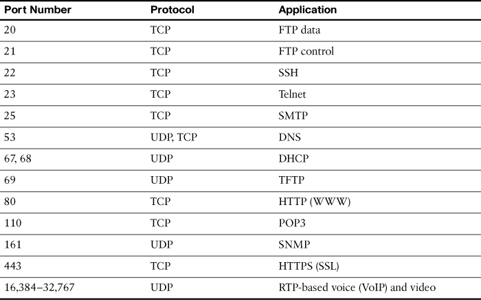
Table 30-5 Popular Applications and Their Well-Known Port Numbers
Error Recovery
Also known as reliability, TCP provides error recovery during data transfer sessions between two end devices that have established a connection. The sequence and acknowledgment fields in the TCP header are used to track every byte of data transfer and ensure that missing bytes are retransmitted.
In Figure 30-3, the Acknowledgment field sent by the web client (4000) implies the next byte to be received; this is called positive acknowledgment.
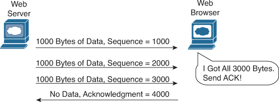
Figure 30-3 TCP Acknowledgment Without Errors
Figure 30-4 depicts the same scenario, except that now we have some errors. The second TCP segment was lost in transmission. Therefore, the web client replies with an ACK field set to 2000. This is called a positive acknowledgment with retransmission (PAR) because the web client is requesting that some of the data be retransmitted. The web server will now resend data starting at segment 2000. In this way, lost data is recovered.
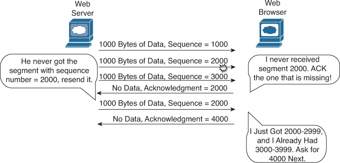
Figure 30-4 TCP Acknowledgment with Errors
Although not shown, the web server also sets a retransmission timer, awaiting acknowledgment, just in case the acknowledgment is lost or all transmitted segments are lost. If that timer expires, the web server sends all segments again.
Flow Control
Flow control is handled by TCP through a process called windowing. The two end devices negotiate the window size when initially establishing the connection; then they dynamically renegotiate window size during the life of the connection, increasing its size until it reaches the maximum window size of 65,535 bytes or until errors occur. Window size is specified in the Window field of the TCP header. After sending the amount of data specified in the window size, the source must receive an acknowledgment before sending the next window size of data.
Connection Establishment and Termination
Connection establishment is the process of initializing sequence and acknowledgment fields and agreeing on port numbers and window size. The three-way connection establishment phase shown in Figure 30-5 must occur before data transfer can proceed.
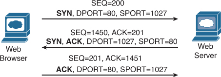
Figure 30-5 TCP Connection Establishment
In the figure, DPORT and SPORT are the destination and source ports. SEQ is the sequence number. In bold are SYN and ACK, which each represent a 1-bit flag in the TCP header used to signal connection establishment. TCP initializes the Sequence Number and Acknowledgment Number fields to any number that fits into the 4-byte fields. The initial Sequence Number is a random 32-bit number generated with each new transmission. The Acknowledgment Number is received back and increments the sender’s sequence number by 1.
After data transfer is complete, a four-way termination sequence occurs that uses an additional flag, called the FIN bit, as shown in Figure 30-6.
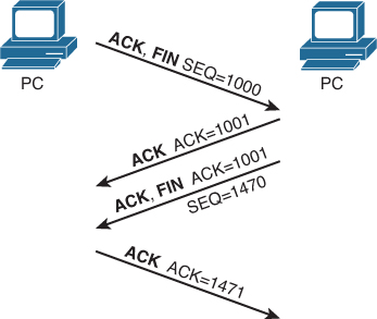
Figure 30-6 TCP Connection Termination
UDP
TCP establishes and terminates connections between endpoints, whereas UDP does not. Therefore, UDP is called a connectionless protocol. It provides no reliability, no windowing, and no reordering of the data. However, UDP does provide data transfer and multiplexing using port numbers, and it does so with fewer bytes of overhead and less processing than TCP. Applications that use UDP are ones that can trade the possibility of some data loss for less delay, such as VoIP. Figure 30-7 compares the two headers.
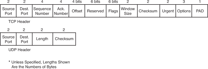
Figure 30-7 TCP and UDP Headers
The TCP/IP Internet Layer
The Internet layer of the TCP/IP model and its Internet Protocol (IP) define addresses so that each host computer can have a different IP address. In addition, the Internet layer defines the process of routing so that routers can determine the best path to send packets to the destination. Continuing with the web page example, IP addresses the data as it passes from the transport layer to the Internet layer:
1. Web client sends an HTTP request.
2. TCP encapsulates the HTTP request.
3. IP encapsulates the transports segment into a packet, adding source and destination addresses.
4. Lower layers process and send the request to the web server.
5. Web server receives HTTP requests and sends a TCP acknowledgment back to the requesting web client.
6. Web server sends the HTTP response down to the transport layer.
7. TCP encapsulates the HTTP data.
8. IP encapsulates the transport segment into a packet, adding source and destination addresses.
9. Lower layers process and send the response to the requesting web client.
10. Requesting web client sends acknowledgment back to the web server.
The operation of IP not only includes addressing but also the process of routing the data from source to destination. IP will be further discussed and reviewed in the upcoming days.
The TCP/IP Network Access Layer
IP depends on the network access layer to deliver IP packets across a physical network. Therefore, the network access layer defines the protocols and hardware required to deliver data across some physical network by specifying exactly how to physically connect a networked device to the physical media over which data can be transmitted.
The network access layer includes a large number of protocols to deal with the different types of media that data can cross on its way from source device to destination device. For example, data might need to travel first on an Ethernet link, then cross a Point-to-Point (PPP) link, then a Frame Relay link, then an Asynchronous Transfer Mode (ATM) link, and then finally an Ethernet link to the destination. At each transition from one media type to another, the network access layer provides the protocols, cabling standards, headers, and trailers to send data across the physical network.
Many times, a local link address is needed to transfer data from one hop to the next. For example, in an Ethernet LAN, Media Access Control (MAC) addresses are used between the sending device and its local gateway router. At the gateway router—depending on the needs of the outbound interface—the Ethernet header might be replaced with a Frame Relay header that will include data-link connection identifier (DLCI) addresses. In Frame Relay, DLCI addresses serve the same purpose as MAC addresses in Ethernet—to get the data across the link from one hop to the next so that the data can continue its journey to the destination. Some protocols, such as Point-to-Point Protocol (PPP), do not need a link address because only one other device is on the link that can receive the data.
With the network access layer, we can now finalize our web page example. The following greatly simplifies and summarizes the process of requesting and sending a web page:
1. Web client sends an HTTP request.
2. TCP encapsulates the HTTP request.
3. IP encapsulates the transport segment into a packet, adding source and destination addresses.
4. Network access layer encapsulates packet in a frame, addressing it for the local link.
5. Network access layer sends the frame out as bits on the media.
6. Intermediary devices process the bits at the network access and Internet layers and then forward the data toward the destination.
7. Web server receives the bits on the physical interface and sends them up through the network access and Internet layers.
8. Web server sends a TCP acknowledgment back to the requesting web client.
9. Web server sends the HTTP response down to the transport layer.
10. TCP encapsulates the HTTP data.
11. IP encapsulates the transport segment into a packet, adding source and destination addresses.
12. Network access layer encapsulates packet in a frame, addressing it for the local link.
13. Network access layer sends the frame out as bits on the media.
14. Lower layers process and send the response to the requesting web client.
15. Response travels back to the source over multiple data links.
16. Requesting web client receives response on the physical interface and sends the data up through the network access and Internet layers.
17. Requesting web client sends a TCP acknowledgment back to the web server.
18. Web page is displayed in requesting device’s browser.
Data Encapsulation Summary
Each layer of the TCP/IP model adds its own header information. As the data travels down through the layers, it is encapsulated with a new header. At the network access layer, a trailer is also added. This encapsulation process can be described in five steps:
Step 1. Create and encapsulate the application data with any required application layer headers. For example, the HTTP OK message can be returned in an HTTP header, followed by part of the contents of a web page.
Step 2. Encapsulate the data supplied by the application layer inside a transport layer header. For end-user applications, a TCP or UDP header is typically used.
Step 3. Encapsulate the data supplied by the transport layer inside an Internet layer (IP) header. IP is the only protocol available in the TCP/IP network model at the Internet layer.
Step 4. Encapsulate the data supplied by the Internet layer inside a network access layer header and trailer. This is the only layer that uses both a header and a trailer.
Step 5. Transmit the bits. The physical layer encodes a signal onto the medium to transmit the frame.
Note
The letters LH and LT stand for link header and link trailer, respectively, and refer to the data link layer header and trailer.
The numbers in Figure 30-8 correspond to the five steps in the list, graphically showing the same encapsulation process.
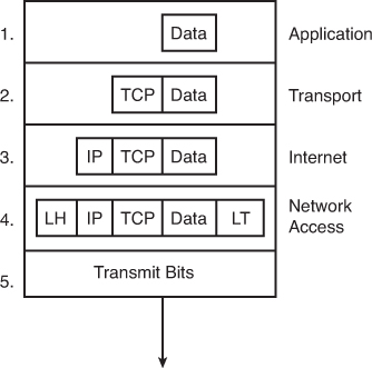
Figure 30-8 Five Steps of Data Encapsulation
Video 30.2—The Data Encapsulation/Decapsulation Process
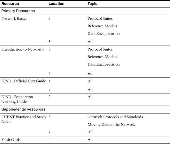
Study Resources
For today’s exam topics, refer to the following resources for more study.
Quiz